----------------CHAPTER
1----------------
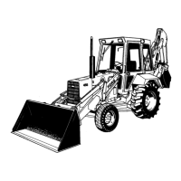
S-22702
Figure 54
Seal Retainer Bolt Tightening Sequence
----------s-22103
Figure 55
Retainer - Block Alignment
1. Straight Edge 2. These Two Faces to
be Flush
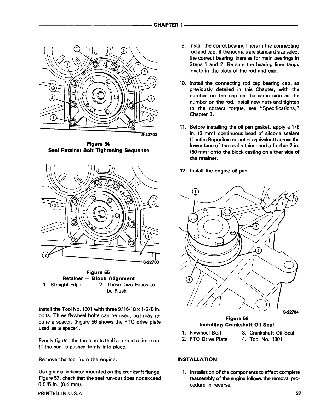
Install the Tool No. 1301 with three 9/16-18 x 1-5/8 in.
bolts. Three flywheel bolts can be used, but may re-
quire a spacer. (Figure
56
shows the PTO drive plate
used as a spacer).
Evenly tighten the three bolts (half a turn at a time) un-
til the seal is pushed firmly into place.
Remove the tool from the engine.
Using a dial indicator mounted on the crankshft flange,
Figure SI, check that the seal run-out does not exceed
0.015 in. (0.4 mm).
PRINTED IN U.S.A.
9. Install the corret bearing liners in the connecting
rod and cap. If the journals are standard size select
the correct bearing liners as for main bearings in
Steps 1 and 2. Be sure the bearing liner tangs
locate in the slots of the rod and cap.
10.
Install the connecting rod cap bearing cap, as
previously detailed in this Chapter, with the
number on the cap on the same side as the
number on the rod. Install new nuts and tighten
to the correct torque, see "Specifications,"
Chapter 3.
11. Before installing the oil pan gasket, apply a 1 /8
in.
(3
mm) continuous bead of silcone sealant
( Loctite Superflex sealant or equivalent) across the
lower face of the seal rateiner and a further
2
in.
(50
mm) onto the block casting on either side of
the retainer.
12. Install the engine oil pan.
S-22704
Figure 56
Installing Crankshaft Oil Seal
1. Flywheel Bolt 3. Crankshaft Oil Seal
2. PTO Drive Plate 4. Tool No. 1301
INSTALLATION
1. Installation of the components to effect complete
reassembly of the engine follows the removal pro-
cedure in reverse.
XI
 Loading...