------------PART
1 -
ENGINE SYSTEMS-------------
The red liners have a thinner wall section than the blue
liners and provide greater clearance. A combination of
red and blue liners may be required to obtain the desired
clearance. If the clearance is greater than specified when
two blue liners are used, a 0.002 in. {0.05 mm) under-
size liner with either a red, blue or another 0.002 in. (0.05
mm) undersize liner should be installed. If any of these
combinations of liners do not produce the specified
clearance, refinish the crankshaft and fit undersize bear-
ings, see "Specifications," Chapter 3.
3. Position the bearing liners in the block and caps
and coat with oil. If the crankshaft has been
refinished fit the correct undersize main bearing
liners. Be sure the bearing surfaces are clean and
the bearing liner tangs align with the slots in the
block and cap.
4. Align the timing mark on the crankshaft gear with
that of the crankshaft drive gear and install the
crankshaft and all bearing caps except for the rear
main bearing. Install the thrust bearing cap with
the bolts finger tight. Pry the crankshaft forward
and the thrust bearing cap rearwards to align the
thrust surfaces and tighten the bolts to the
specified torque, keeping the bearing cap in the
correct position.
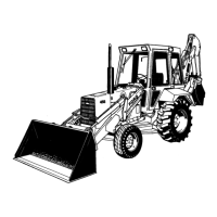
5. Check the crankshaft end play with a dial indicator
gauge, Figure 52. Move the crankshaft rearwards
and set the dial indicator to zero. Pry the
crankshaft forward and if the end play exceeds the
limit, see "Specifications," Chapter 3, install new
thrust bearing liners. If the end play is less than
the specified limit, inspect the thrust bearing sur-
faces for burrs, scratches or dirt. If the thrust sur-
faces are not defective or dirty, realign the thrust
bearings as detailed in Step 4.
6. Thoroughly clean the rear bearing cap and cylinder
block. Parts must be dry and free of oil and dirt.
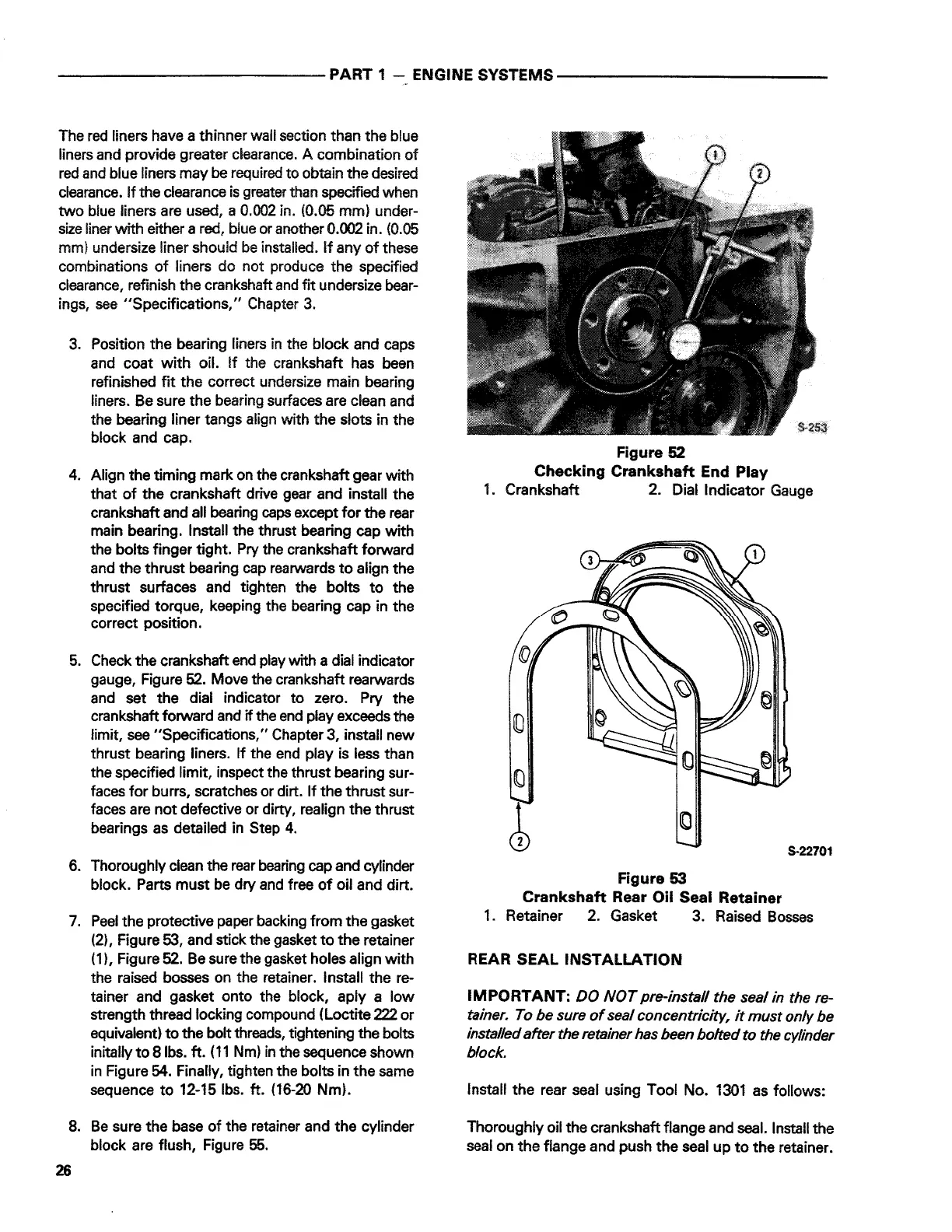
7. Peel the protective paper backing from the gasket
(2), Figure 53, and stick the gasket to the retainer
( 1), Figure 52. Be sure the gasket holes align with
the raised bosses on the retainer. Install the re-
tainer and gasket onto the block, aply a low
strength thread locking compound (Loctite 222 or
equivalent) to the bolt threads, tightening the bolts
initally to 8 lbs. ft. (11 Nm) in the sequence shown
in Figure 54. Finally, tighten the bolts in the same
sequence to 12-15 lbs. ft. (16-20 Nm).
8. Be sure the base of the retainer and the cylinder
block are flush, Figure 55.
26
Figure 52
Checking Crankshaft End Play
1. Crankshaft 2. Dial Indicator Gauge
(0
S-22701
Figure 53
Crankshaft Rear Oil Seal Retainer
1. Retainer 2. Gasket 3. Raised Bosses
REAR SEAL INSTALLATION
IMPORTANT:
DO NOT pre-install the seal in the re-
tainer. To be sure of seal concentriclty, it must only be
installed after the retainer has been bolted to the cylinder
block.
Install the rear seal using Tool No. 1301 as follows:
Thoroughly oil the crankshaft flange and seal. Install the
seal on the flange and push the seal up to the retainer.
 Loading...