SECTION A DRIVING
THE TRACTOR
DRIVING
THE TRACTOR
SECTION A
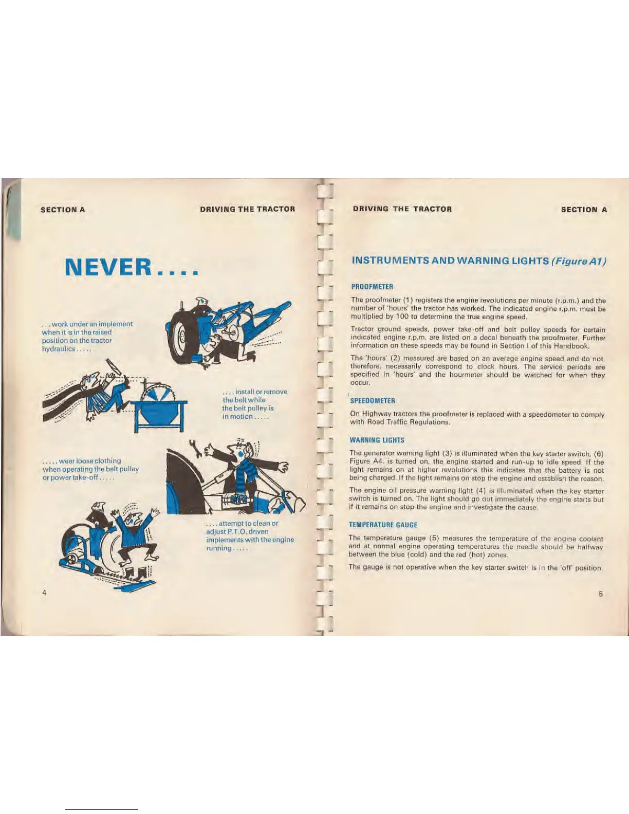
NEVER
. . .
work under an implement
when it is in the
raised
position
on the
tractor
hydraulics
L
J
install or remove
the belt while
the belt pulley is
n motion
"
INSTRUMENTS
AND WARNING
LIGHTS (Figure
A1)
PROOFMETER
The proofmeter
(1
) registers the engine revolutions per minute
(r.p.m.) and the
number
of 'hours' the tractor has worked.
The indicated engine r.p.m. must
be
multiplied by 100 to determine the
true engine speed.
Tractor ground
speeds, power take-off and bolt pulley
speeds for certain
indicated
engine
r.p.m.
are listed on a decal
beneath the proofmeter. Further
information
on these speeds may be found
in Section I of this Handbook.
The 'hours'
(2)
measured are
based on an average engine
speed and do not,
therefore, necessarily correspond
to clock hours. The
service periods are
specified
in 'hours' and the hourmeter should
be watched for when they
occur.
SPEEDOMETER
On Highway
tractors the proofmeter
is
replaced
with a speedometer to comply
with
Road Traffic Regulations.
?3
wear loose clothing
when
operating the belt pulley
or power
take-off
attempt to clean or
adjust P.T.O. driven
implements with the engine
running
r.
i:
WARNING
LIGHTS
The generator warning
light
(3)
is illuminated when
the key starter switch,
(6)
Figure A4, is
turned on, the engine
started and run-up to idle speed. If the
light remains on at higher revolutions
this indicates that the
battery is not
being
charged. If the light
remains on stop the engine and establish
the reason.
The engine oil
pressure warning light
(4)
is illuminated
when the key starter
switch is turned on. The light should
go out
immediately
the engine starts
but
if it remains on stop the engine
and investigate ihe cause.
TEMPERATURE GAUGE
The
temperature gauge
(5)
measures
the temperature of the engine
coolant
and at normal engine operating temperatures
the needle should
be
halfway
between the blue (cold)
and the red (hot) zones.
The
gauge is not operative when
the
key
starter switch is in the 'off' position.
 Loading...


