Every 6000 miles or 6 Months 1•9
1
1 Simply pull the oil filler cap from the rocker
cover and, where applicable, disconnect the
hose(s) from the cap.
2 Inspect the filler cap, and if necessary clean
the cap using clean petrol to remove any
deposits.
3 Ensure that the cap is completely dry
before refitting.
1 Visually inspect the engine joint faces,
gaskets and seals for any signs of water or oil
leaks. Pay particular attention to the areas
around the rocker cover, cylinder head, oil
filter and sump joint faces. Bear in mind that
over a period of time some very slight
seepage from these areas is to be expected
but what you are really looking for is any
indication of a serious leak. Should a leak be
found, renew the offending gasket or oil seal
by referring to the appropriate Chapter(s) in
this manual.
2 Similarly, check the transmission for oil
leaks, and investigate and rectify and
problems found.
3 Check the security and condition of all the
engine related pipes and hoses. Ensure that
all cable-ties or securing clips are in place and
in good condition. Clips which are broken or
missing can lead to chafing of the hoses,
pipes or wiring which could cause more
serious problems in the future.
4 Carefully check the condition of all coolant,
fuel and brake hoses. Renew any hose which
is cracked, swollen or deteriorated. Cracks
will show up better if the hose is squeezed.
Pay close attention to the hose clips that
secure the hoses to the system components.
Hose clips can pinch and puncture hoses,
resulting in leaks. If wire type hose clips are
used, it may be a good idea to replace them
with screw-type clips.
5 With the vehicle raised, inspect the fuel
tank and filler neck for punctures, cracks and
other damage. The connection between the
filler neck and tank is especially critical.
Sometimes a rubber filler neck or connecting
hose will leak due to loose retaining clamps or
deteriorated rubber.
6 Similarly, inspect all brake hoses and metal
pipes. If any damage or deterioration is
discovered, do not drive the vehicle until the
necessary repair work has been carried out.
Renew any damaged sections of hose or pipe.
7 Carefully check all rubber hoses and metal
fuel lines leading away from the petrol tank.
Check for loose connections, deteriorated
hoses, crimped lines and other damage. Pay
particular attention to the vent pipes and
hoses which often loop up around the filler
neck and can become blocked or crimped.
Follow the lines to the front of the vehicle
carefully inspecting them all the way. Renew
damaged sections as necessary.
8 From within the engine compartment,
check the security of all fuel hose attachments
and pipe unions, and inspect the fuel hoses
and vacuum hoses for kinks, chafing and
deterioration.
9 Where applicable, check the condition of
the oil cooler hoses and pipes.
10 Check the condition of all exposed wiring
harnesses.
11 Also check the engine and transmission
components for signs of fluid leaks.
Check the tightness of the exhaust
manifold securing nuts using a torque wrench.
Note: Before carrying out any carburettor
adjustment, ensure that the contact breaker
points, ignition timing and spark plug gaps (as
applicable) are set as specified and that the
distributor is operating correctly (where
applicable). To carry out the adjustments an
accurate tachometer will be required and the
use of an exhaust gas analyser (CO meter) is
also preferable.
Models with Ford VV carburettor
Idle speed
1 With the engine at normal operating
temperature, connect a tachometer in
accordance with the manufacturer’s
instructions.
2 Disconnect the wiring multi-plug from the
radiator cooling fan thermostatic switch in the
thermostat housing and bridge the two
contacts in the plug using a suitable length of
wire. This is necessary so that the cooling fan
runs continuously during adjustment.
3 On automatic transmission models slacken
the adjuster screw on the throttle valve shaft
lever to give clearance of 2 to 3 mm (0.079 to
0.118 in) - see Chapter 7, Part B.
4 Ensure that the air cleaner is fitted and that
its vacuum hoses are not in any way trapped
or pinched, particularly between the air cleaner
body and the top face of the carburettor.
5 Run the engine at 3000 rpm for 30 seconds,
then allow it to idle and note the idle speed. If
using an exhaust gas analyser it should be
noted that initially the CO% reading will rise,
but then fall and stabilise after a period of 5 to
25 seconds. The CO reading should then be
as specified.
Idle mixture
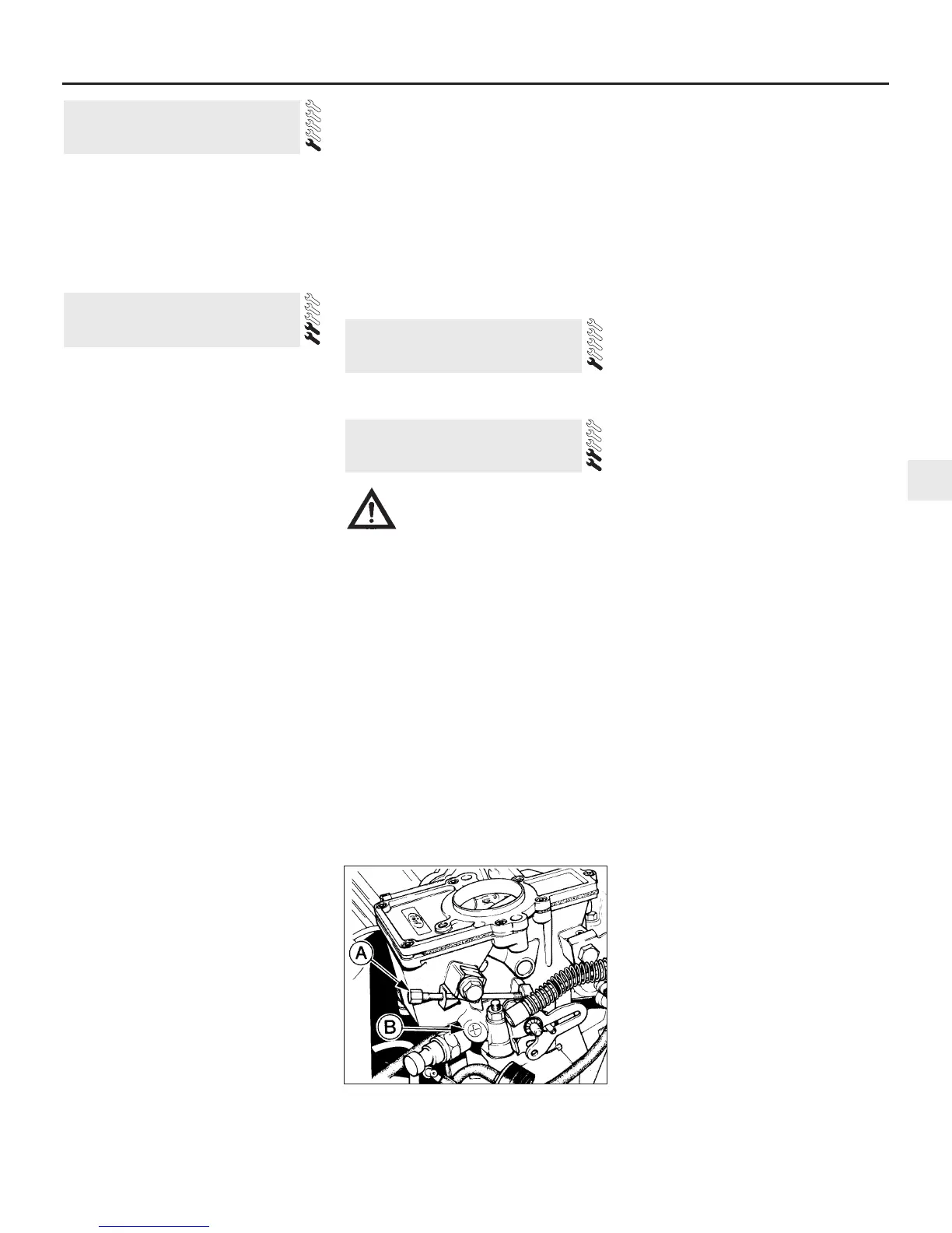
6 If necessary, adjust the idle speed
adjustment screw to give the specified idle
speed (see illustration).
7 Adjustment of the CO content (mixture) is
not normally required during routine
maintenance, but if the reading noted in
paragraph 5 is not as given in the
Specifications first remove the tamperproof
plug, prising it free using a small screwdriver.
8 Run the engine at 3000 rpm for 30 seconds,
then allow it to idle. Adjust the mixture screw
(see illustration 10.6) within 30 seconds. If
more time is required run the engine at 3000
rpm again for 30 seconds.
9 Adjust the idle speed if necessary and
recheck the CO content.
10 Fit a new tamperproof plug to the mixture
adjuster screw on completion. It should be
noted that mixture adjustment without a CO
analyser is not accurate and therefore not
recommended.
11 On completion disconnect the
instruments, remove the cooling fan bridging
wire and reconnect the multi-plug.
12 On automatic transmission models adjust
the downshift linkage (Chapter 7, Part B).
Models with Weber 2V carburettor
13 The procedure is the same as for the Ford
VV carburettor as described previously in this
Section, but the adjusting screw locations are
as shown (see illustrations).
Models with Bosch K-Jetronic
fuel injection system
14 The idle speed and fuel mixture
adjustments will normally only be required
after the installation of new components.
10 Idle speed and mixture
adjustment
9 Exhaust manifold nut check -
RS Turbo models
8 Fluid leak check
7 Oil filler cap cleaning - OHV
and HCS engines
10.6 Idle speed adjustment screw (A) and
mixture adjustment screw (B) - Ford VV
carburettor
Caution: Certain adjustment
points in the fuel system are
protected by “tamperproof”
caps, plugs or seals. In some
EEC countries (though not yet in the UK)
it is an offence to drive a vehicle with
broken or missing tamperproof seals.
Before disturbing a tamperproof seal,
satisfy yourself that you will not be
breaking any local or national laws by
doing so, and fit a new seal after
adjustment is complete where required by
law. Do not break tamperproof seals on a
vehicle which is still under warranty.
 Loading...