Refer to the caution at the beginning of this
Section before proceeding.
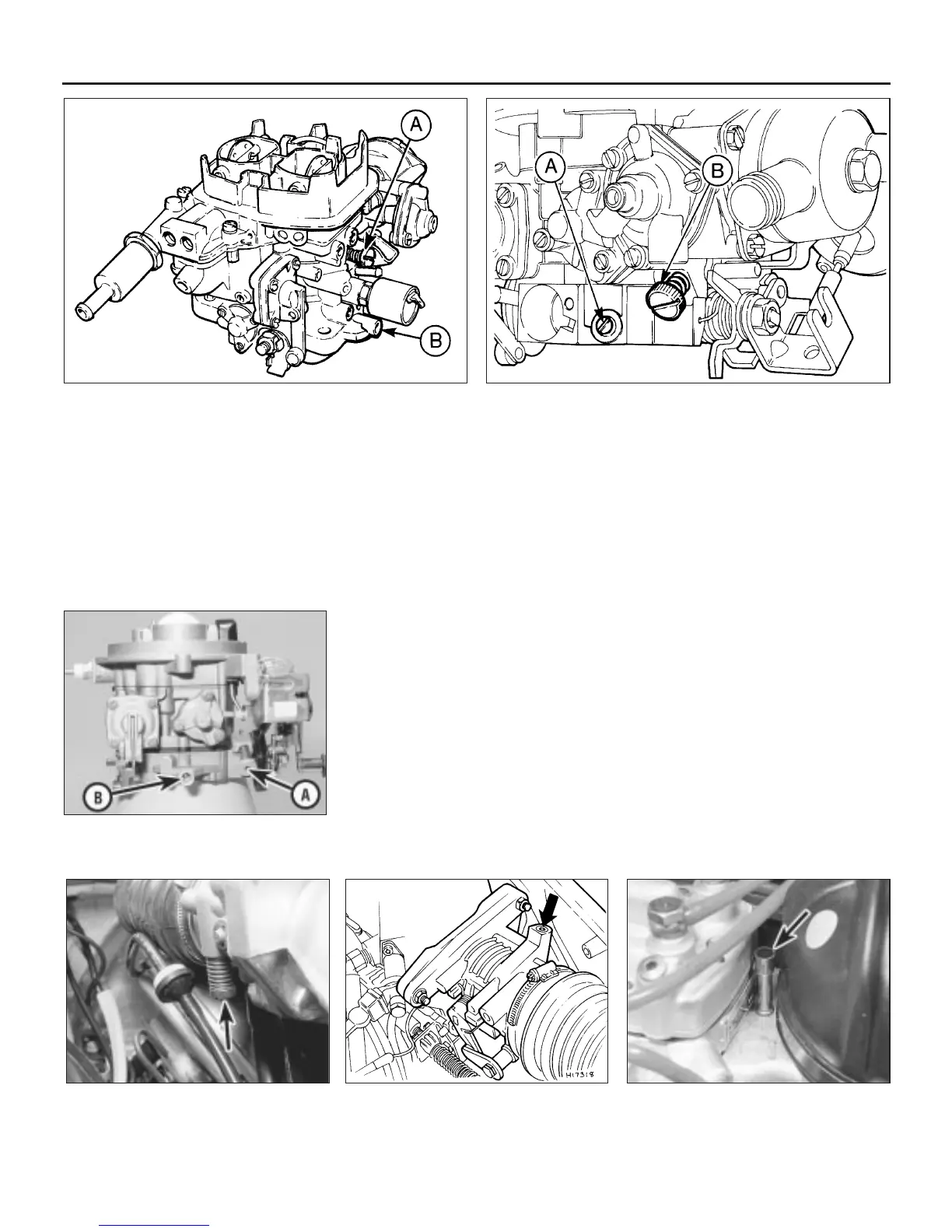
15 On early models the idle speed
adjustment screw is located on the rear of the
throttle housing, but access is severely limited
unless the heater plenum chamber top cover
is removed as described in Chapter 4, Part B
(see illustration).
16 On later models the idle speed adjustment
screw is located on top of the throttle housing
beneath a tamperproof plug (see illustration).
Hook out the plug with a sharp pointed tool to
gain access.
17 Before making any adjustments, warm the
engine up to normal operating temperature
and connect a tachometer in accordance with
the manufacturer’s instructions.
18 Increase the engine speed to 3000 rpm
and hold it at this speed for 30 seconds, then
allow the engine to idle, check the tachometer
reading and if necessary turn the idle speed
adjustment screw as required until the engine
is idling at the specified speed.
19 To check the mixture adjustment an
exhaust gas analyser is needed and should be
connected in accordance with the
manufacturer’s instructions. A 3 mm Allen key
will also be required to make any adjustments.
20 Before making any adjustments to the
mixture, ensure that the idle speed is correct.
21 Remove the tamperproof plug from the
top of the mixture adjustment screw tube on
top of the fuel distributor (see illustration).
22 Stabilise the exhaust gases (paragraph 18).
23 Insert the Allen key into the mixture screw
tube and engage the adjusting screw. Turn
the screw as necessary until the correct CO
reading is obtained, then if required readjust
the idling speed.
24 If the mixture adjustment cannot be
finalised within 30 seconds from the moment
of stabilising the exhaust gases, repeat the
operations in paragraph 18 before continuing
the adjustment procedure.
25 On completion fit a new tamperproof plug
and disconnect the tachometer and exhaust
gas analyser.
Models with Bosch KE-Jetronic
fuel injection system
26 The idle speed and fuel mixture
adjustments will normally only be required
after the installation of new components.
27 The idle speed adjustment screw is
located on the side of the throttle housing
(see illustration).
28 Before making any adjustments, warm the
engine up to normal operating temperature
and connect a tachometer in accordance with
the manufacturer’s instructions.
29 Disconnect the wiring multi-plug at the
pressure actuator on the side of the fuel
distributor (see illustration).
30 Increase the engine speed to 3000 rpm
and hold it at this speed for 30 seconds, then
allow the engine to idle. Check the
tachometer reading and if necessary turn the
1•10 Every 6000 miles or 6 Months
10.16 K-Jetronic system idle speed
adjustment screw (arrowed) on later
models
10.13b Weber 2V carburettor mixture adjustment screw (A) and
idle speed adjustment screw (B) - 1.6 litre models
10.15 Idle speed adjustment screw
(arrowed) on early K-Jetronic systems
10.13c Idle speed screw (A) and mixture
adjustment screw (B) on Weber 2V TLDM
carburettor (1.1 and 1.3 HCS engines)
10.13a Weber 2V carburettor idle speed adjustment screw (A) and
mixture screw (B) - XR3 and 1.4 litre models
10.21 K-Jetronic system mixture
adjustment screw location (arrowed)
 Loading...