Every 6000 miles or 6 Months 1•11
1
idle speed adjustment screw as required until
the engine is idling at the specified speed.
31 To check the mixture adjustment an
exhaust gas analyser is needed and should be
connected in accordance with the
manufacturer’s instructions. A 3 mm Allen key
will also be required to make any adjustments.
32 Before proceeding ensure that the idle
speed is correct.
33 Unscrew the tamperproof plug from the
mixture adjustment orifice on top of the fuel
distributor (see illustration).
34 Stabilise the exhaust gases (paragraph 30).
35 Insert the Allen key into the mixture
adjustment orifice and push down to engage
the adjustment screw. Turn the adjustment
screw clockwise to increase the CO reading
and anti-clockwise to decrease it. Remove the
Allen key, plug the orifice and check the CO
reading.
36 If the mixture adjustment cannot be
finalised within 30 seconds from the moment
of stabilising the exhaust gases, repeat the
operations in paragraph 30 before continuing
the adjustment procedure. Make sure that the
Allen key is removed before increasing the
engine speed otherwise the fuel distributor
will be damaged.
37 Continue adjustment until the correct CO
reading is obtained, then if necessary readjust
the idle speed.
38 Refit the tamperproof screw and
reconnect the pressure actuator multi-plug.
Disconnect the tachometer and exhaust gas
analyser.
Models with Central (single-point)
Fuel Injection (CFI) system
39 Both the idle speed and mixture are
controlled by the engine management system.
Adjustment requires the use of specialist
equipment. If the idle speed is suspected of
being incorrect, the vehicle must be taken to a
Ford dealer for diagnostic checks and, if
necessary, adjustment.
Models with Electronic Fuel
Injection (EFI) system
40 Idle speed is controlled by the EEC IV
module, and cannot be adjusted.
41 To adjust the mixture (CO content), first
run the engine until it reaches normal
operating temperature.
42 Connect a CO meter and a tachometer in
accordance with the manufacturer’s
instructions.
43 Clear any excess fuel in the inlet manifold
by running the engine at 3000 rpm for
approximately 15 seconds, then allow the
engine to idle.
44 Wait for the test instrument readings to
stabilise, then record the CO content and the
idle speed.
45 If adjustment of the CO content is
required, remove the tamperproof cap from
the CO adjustment potentiometer (located on
the wing panel behind the left-hand
suspension turret) and adjust the screw to
obtain the correct CO setting at the specified
idle speed (see illustration). Note that any
adjustment must be made within 30 seconds
of the instrument readings stabilising,
otherwise the procedure described in
paragraph 43 must be repeated.
46 On completion of adjustment, stop the
engine and disconnect all test equipment. Fit
a new tamperproof cap to the CO adjustment
potentiometer.
1 Where applicable, remove the distributor
cap and thoroughly clean it inside and out
with a dry lint-free cloth. Examine the four HT
lead segments inside the cap. If the segments
appear badly burnt or pitted, renew the cap.
Make sure that the carbon brush in the centre
of the cap is free to move and that it protrudes
significantly from its holder.
2 Check the distributor cap for signs of
tracking (indicated by thin black lines on the
surface of the cap). Renew the cap if tracking
is evident.
3 Wipe clean the HT leads and the coil tower.
4 Check the condition and security of all
leads and wiring associated with the ignition
system. Make sure that no chafing is
occurring on any of the wires and that all
connections are secure, clean and free from
corrosion.
1 Remove the distributor cap and the rotor
arm.
2 Apply a couple of drops of light oil to the
felt pad in the top of the shaft.
3 Wipe clean the distributor cam, then apply
a trace of high melting-point grease to the
four cam lobes.
4 Refit the rotor arm and the distributor cap.
1 Spring back the retaining clips or undo the
screws as appropriate and lift off the
distributor cap.
2 Withdraw the rotor arm from the distributor
shaft.
3 Using a screwdriver, gently prise the
contact breaker points open to examine the
condition of their faces. If they are rough,
pitted or dirty they should be renewed as
described in the next Section.
4 Assuming that the points are in a satisfactory
condition or that they have just been renewed,
the gap between the two faces should be
checked and if necessary adjusted. This can be
done using feeler blades as described in the
following paragraphs, or preferably by using
the more accurate dwell angle method as
described from paragraph 8 onwards.
13 Contact breaker points
adjustment - models with
contact breaker distributor
12 Distributor lubrication -
models with contact breaker
distributor
11 Ignition system component
check
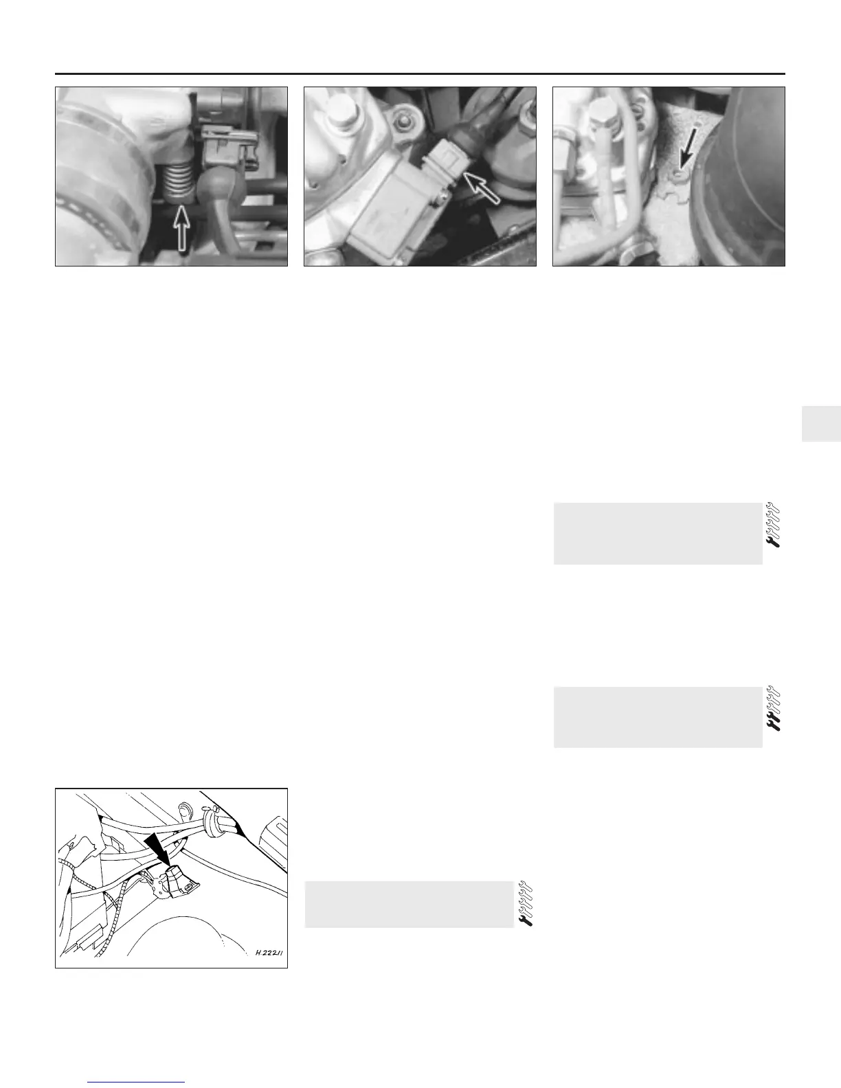
10.29 Pressure actuator wiring multi-plug
(arrowed) - KE-Jetronic system
10.27 Idle speed adjustment screw
(arrowed) on KE-Jetronic system
10.45 CO adjustment potentiometer
location (arrowed) - 1.6 EFI engine
10.33 KE-Jetronic system mixture
adjustment tamperproof plug (arrowed)
 Loading...