Rear Electronic Module (REM) Diagnostic Trouble Code (DTC) Index
Instrument Cluster Diagnostic Trouble Code (DTC) Index
Symptom Chart
Connector Circuit Reference
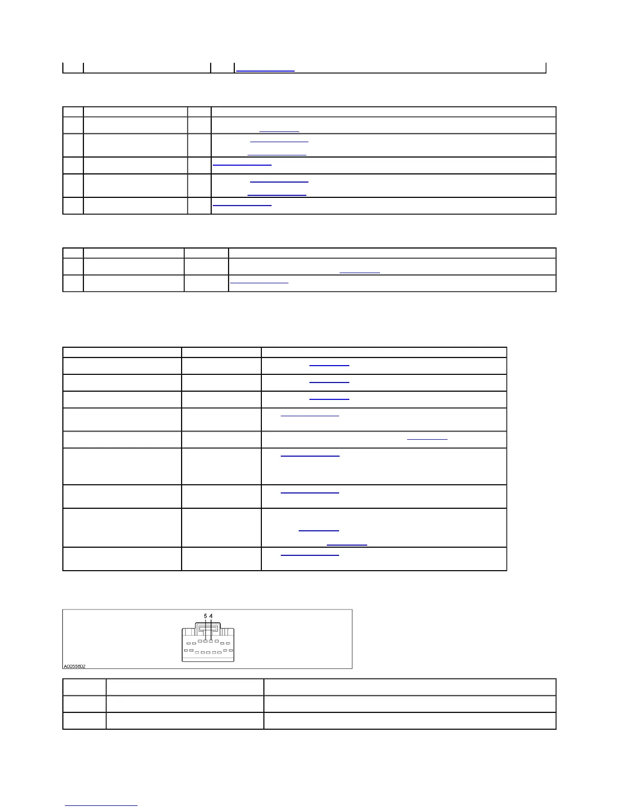
Front Electronic Module (FEM) C201a
B1505 Lamp Turn Signal Right Circuit Short to Battery FEM GO to Pinpoint Test Q.
DTC Description Source Action
B1342 ECU Is Defective REM CLEAR and DOCUMENT the DTCs. CARRY OUT the instrument cluster self-test. INSTALL a new REM if DTC B1342 is retrieved
again. REFER to Section 418-00.
B2529 Left Rear Turn Lamp Circuit Failure REM If inoperative, GO to Pinpoint Test N.
If always on, GO to Pinpoint Test O.
B2530 Left Rear Turn Lamp Circuit Short to
Battery
REM GO to Pinpoint Test N.
B2535 Right Rear Turn Lamp Circuit Failure REM If inoperative, GO to Pinpoint Test N.
If always on, GO to Pinpoint Test O.
B2536 Right Rear Turn Lamp Circuit Short to
Battery
REM GO to Pinpoint Test N.
DTC Description Source Action
B1342 ECU Is Defective Instrument
cluster
CLEAR and DOCUMENT the DTCs. CARRY OUT the instrument cluster Self-Test. INSTALL a new instrument cluster if
DTC B1342 is retrieved again. REFER to Section 413-00.
B1875 Turn Signal/Hazard Switch Signal
Circuit Failure
Instrument
cluster
GO to Pinpoint Test S.
Symptom Chart
Condition Possible Sources Action
No communication with the front
electronic module (FEM)
Circuitry.
FEM.
REFER to Section 418-00.
No communication with the rear
electronic module (REM)
Circuitry.
REM.
REFER to Section 418-00.
No communication with the
instrument cluster module
Circuitry.
Instrument cluster.
REFER to Section 413-00.
The turn signal lamps are
inoperative
Circuitry.
Multifunction switch.
Instrument cluster.
GO to Pinpoint Test P.
The turn signal lamps are always on
Multifunction switch.
INSTALL a new multifunction switch. REFER to Section 211-00. TEST the system for
normal operation.
One turn signal lamp is inoperative
Circuitry.
Rear electronic
module (REM).
Front electronic
module (FEM).
GO to Pinpoint Test Q.
One turn signal lamp is always on
Circuitry.
Front electronic
module (FEM).
GO to Pinpoint Test R.
The hazard lamps are inoperative
Multifunction switch.
CARRY OUT the multifunction switch component test.
If the multifunction switch is OK, INSTALL a new instrument cluster. REFER to
Section 413-00. TEST the system for normal operation.
If the multifunction switch is not OK, INSTALL a new multifunction switch.
REFER to Section 211-00. TEST the system for normal operation.
The hazard lamps are always on
Circuitry.
Multifunction switch.
Instrument cluster.
GO to Pinpoint Test S.
Pin Number
(s) Circuit Designation/Description Normal Condition/Measurement
4 31S-LG18 (BK/YE) RH front turn lamp control ground
circuit
Less than 5 ohms between the FEM and the RH front turn lamp. Greater than 10 volts with the ignition switch
ON.
5 31S-LG11 (BK/WH) LH front turn lamp control ground
circuit
Less than 5 ohms between the FEM and the LH front turn lamp. Greater than 10 volts with the ignition switch
ON.
2003 Thunderbird Workshop Manual
http://www.fordtechservice.dealerconnection.com/pubs/content/~WS3D/~MUS~LEN/19/S