Multifunction Switch C202
Instrument Cluster C220b
LH Front Parking/Turn Lamp C1023, RH Front Parking/Turn Lamp C1043
Pinpoint Test P: The Turn Signal Lamps Are Inoperative
Normal Operation
The instrument cluster sends out a voltage reference signal through circuit 8-LG43 (WH/VT) to the multifunction switch. The return signal is carried through circuit 9-LG43 (BN/WH) (shared
with the high beam circuit) back to the instrument cluster. When the multifunction switch is placed in the RH or LH turn positions, the voltage signal sent by the instrument cluster passes
through a resistor within the multifunction switch (specific to LH and RH turn positions) before returning to instrument cluster.
Possible Causes
circuit 8-LG43 (WH/VT) open, short to ground or short to power
multifunction switch
instrument cluster
PINPOINT TEST P: THE TURN SIGNAL LAMPS ARE INOPERATIVE
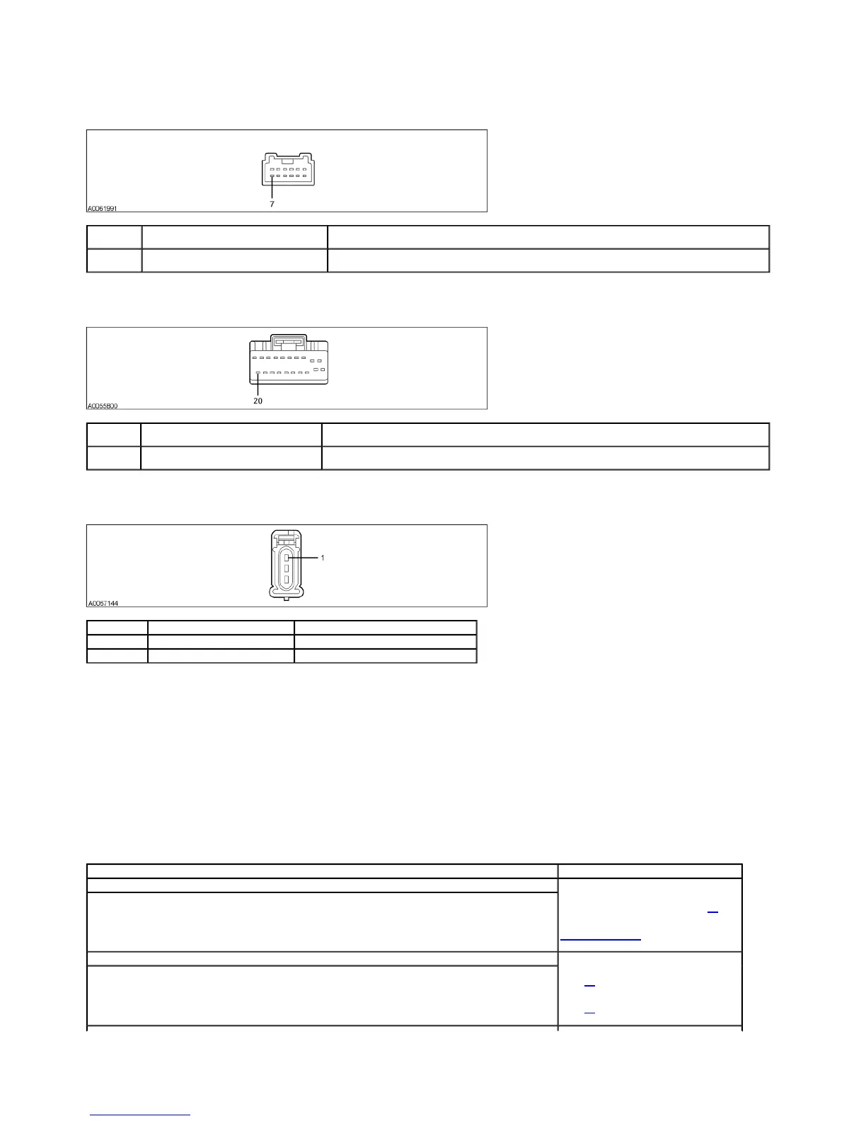
Pin Number
(s) Circuit Designation/Description Normal Condition/Measurement
7 8-LG43 (WH/VT) multifunction switch signal
output circuit
Less than 5 ohms between the multifunction switch and the instrument cluster. Greater than 10,000 ohms between the
instrument cluster and ground.
Pin Number
(s) Circuit Designation/Description Normal Condition/Measurement
20 8-LG43 (WH/VT) multifunction switch signal
output circuit
0 voltage, less than 5 ohms between the instrument cluster and the multifunction switch. Greater than 10,000 ohms
between the instrument cluster and ground.
Pin Number(s) Circuit Designation/Description Normal Condition/Measurement
1 (1023) 29S-LF7 (OG/BU) switched B+ circuit Greater than 10 volts with the ignition switch ON.
1 (1043) 29S-LF16 (OG/GN) switched B+ circuit Greater than 10 volts with the ignition switch ON.
Test Step Result / Action to Take
P1 CHECK THE HIGH BEAM OPERATION
Ignition ON.
Turn the headlamp switch to the headlamps ON position.
Place the multifunction switch in the high beam position.
Do the high beams operate correctly?
Yes
TURN the headlamp switch OFF. GO to P2.
No
GO to Pinpoint Test B to diagnose the high
beams.
P2 CHECK THE MULTIFUNCTION SWITCH OUTPUT
Ignition OFF.
Connect the scan tool.
Ignition ON.
Monitor the instrument cluster turn signal status PID while placing the multifunction switch in the RH and then LH turn
positions.
Does the PID match with the multifunction switch positions?
Yes
GO to P6.
No
GO to P3.
2003 Thunderbird Workshop Manual
http://www.fordtechservice.dealerconnection.com/pubs/content/~WS3D/~MUS~LEN/19/S