Pinpoint Test Q: One Turn Signal Lamp Is Inoperative
Normal Operation
Power is supplied from the central junction box (CJB) to the LH front turn signal lamp through circuits 29S-LF3 (OG/YE) and 29S-LF7 (OG/BU). The ground for the LH front turn signal lamp
is passed through circuit 31S-LG11 (BK/WH) to the front electronic module (FEM). Power is supplied from the CJB to the RH front turn signal lamp through circuits 29S-LF4 (OG/BU) and
29S-LF16 (OG/GN). The ground for the RH front turn signal lamp is passed through circuit 31S-LG18 (BK/YE) to the FEM. The FEM and rear electronic module (REM) individually control
the ground circuits for the turn signal lamps. The timed on/off cycle is determined in the instrument cluster programming and is set to flash approximately 80 times per minute if both the
front and rear turn signal lamps are good. If any turn signal lamp is not good, the instrument cluster will flash the remaining working turn signal lamp(s) approximately 160 times per minute.
Possible Causes
circuit 29S-LF7 (OG/BU) open
circuit 29S-LF16 (OG/GN) open
circuit 31S-LG11 (BK/WH) open or short to power
circuit 31S-LG18 (BK/YE) open or short to power
FEM
REM
PINPOINT TEST Q: ONE TURN SIGNAL LAMP IS INOPERATIVE
P3 CHECK THE MULTIFUNCTION SWITCH
Ignition OFF.
Disconnect: Multifunction Switch C202.
Carry out the multifunction switch component test.
Refer to Wiring Diagrams Cell 149 for component testing.
Is the multifunction switch OK?
Yes
GO to P4.
No
INSTALL a new multifunction switch. REFER to
Section 211-00. TEST the system for normal
operation.
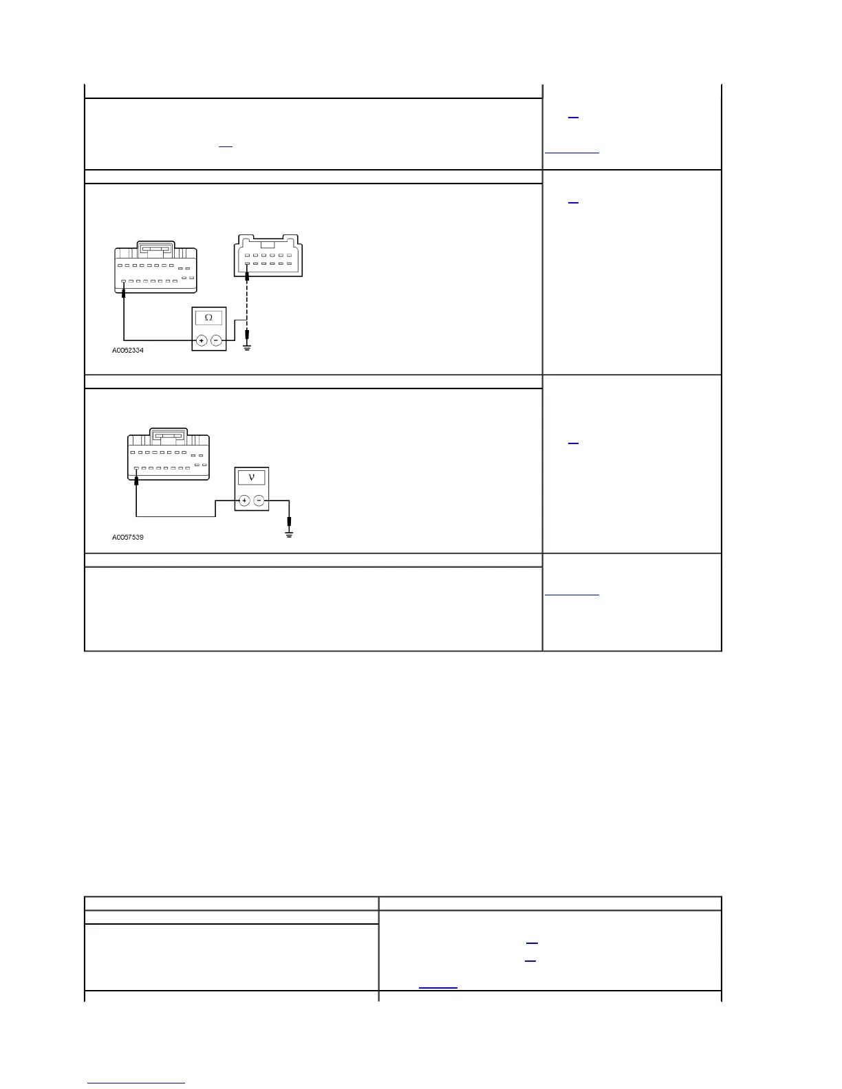
P4 CHECK CIRCUIT 8-LG43 (WH/VT) FOR AN OPEN OR SHORT TO GROUND
Disconnect: Instrument Cluster C220b.
Measure the resistance between the instrument cluster C220b-20, circuit 8-LG43 (WH/VT), harness side and the
multifunction switch C202-7, circuit 8-LG43 (WH/VT), harness side; and between the instrument cluster C220b-20, circuit
8-LG43 (WH/VT), harness side and ground.
Is the resistance less than 5 ohms between the instrument cluster and the multifunction switch; and greater than
10,000 ohms between the instrument cluster and ground?
Yes
GO to P5.
No
REPAIR the circuit. TEST the system for normal
operation.
P5 CHECK CIRCUIT 8-LG43 (WH/VT) FOR SHORT TO POWER
Ignition ON.
Measure the voltage between the instrument cluster C220b-20, circuit 8-LG43 (WH/VT), harness side and ground.
Is any voltage present?
Yes
REPAIR the circuit. TEST the system for normal
operation.
No
GO to P6.
P6 CHECK FOR INSTRUMENT CLUSTER OPERATION
Ignition OFF.
Disconnect all instrument cluster connectors.
Check for:
corrosion
pushed-out pins
Connect all instrument cluster connectors and make sure they seat correctly.
Operate the system and verify the concern is still present.
Is the concern still present?
Yes
INSTALL a new instrument cluster. REFER to
Section 413-00. TEST the system for normal
operation.
No
The system is operating correctly at this time.
Concern may have been caused by a loose or
corroded connector. REPEAT the self-test.
Test Step Result / Action to Take
Q1 CHECK THE STOPLAMPS
Press the brake pedal and observe the stoplamps.
Do the stoplamps operate correctly?
Yes
If a front turn signal is inoperative, GO to Q2.
If a rear turn signal is inoperative, GO to Q5.
No
REFER to Stoplamps in this section to continue diagnostics.
2003 Thunderbird Workshop Manual
http://www.fordtechservice.dealerconnection.com/pubs/content/~WS3D/~MUS~LEN/19/S