Pinpoint Test R: One Turn Signal Lamp Is Always On
Normal Operation
Power is supplied from the central junction box (CJB) to the LH front turn signal lamp through circuits 29S-LF3 (OG/YE) and 29S-LF7 (OG/BU). The ground for the LH front turn signal lamp
is passed through circuit 31S-LG11 (BK/WH) to the front electronic module (FEM). Power is supplied from the CJB to the RH front turn signal lamp through circuits 29S-LF4 (OG/BU) and
29S-LF16 (OG/GN). The ground for the RH front turn signal lamp is passed through circuit 31S-LG18 (BK/YE) to the FEM. The FEM individually controls the ground circuits for the front turn
signal lamps. The timed on/off cycle is determined in the instrument cluster programming and is set to flash approximately 80 times per minute if both the front and rear turn signal lamps
are good. If any turn signal lamp is not good, the instrument cluster will flash the remaining working turn signal lamp(s) approximately 160 times per minute.
Possible Causes
circuit 31S-LG11 (BK/WH) short to ground
circuit 31S-LG18 (BK/YE) short to ground
FEM
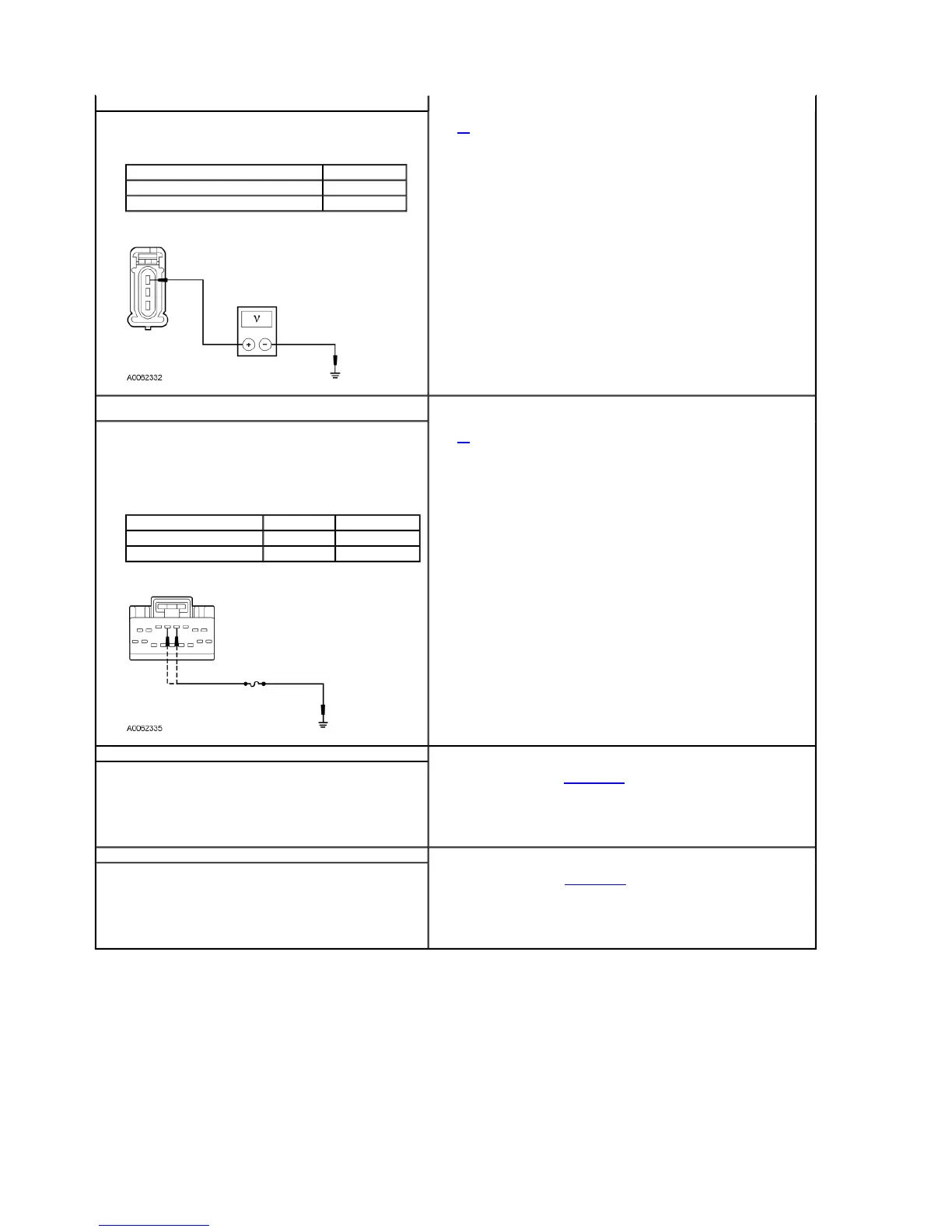
Q2 CHECK THE POWER SUPPLY TO THE TURN SIGNAL LAMP
Ignition OFF.
Disconnect: Inoperative Turn Signal Lamp.
Ignition ON.
Measure the voltage between the inoperative lamp and ground as follows:
Is the voltage greater than 10 volts?
Inoperative Turn Signal Lamp Connector-Pin Circuit
LH front parking/turn signal lamp C1023-1 29S-LF7 (OG/BU)
RH front parking/turn signal lamp C1043-1 29S-LF16 (OG/GN)
Yes
GO to Q3.
No
REPAIR the circuit in question. CLEAR the DTCs. TEST the system for normal operation.
Q3 CHECK THE CONTROL GROUND CIRCUIT FOR AN OPEN OR SHORT
TO POWER
Ignition OFF.
Connect: Inoperative Turn Signal Lamp.
Disconnect: FEM C201a.
Ignition ON.
NOTE: If the fuse in the jumper wire fails, repair the circuit for short to
power.
Connect a fused (5A) jumper wire between the FEM and ground as
follows:
Does the inoperative lamp now illuminate?
Inoperative Turn Signal Lamp FEM Connector Circuit
LH front parking/turn signal lamp FEM C201a-5 31S-LG11 (BK/WH)
RH front parking/turn signal lamp FEM C201a-4 31S-LG18 (BK/YE)
Yes
GO to Q4.
No
REPAIR the circuit in question. CLEAR the DTCs. TEST the system for normal operation.
Q4 CHECK FOR FEM OPERATION
Ignition OFF.
Disconnect all FEM connectors.
Check for:
corrosion
pushed-out pins
Connect all FEM connectors and make sure they seat correctly.
Operate the system and verify the concern is still present.
Is the concern still present?
Yes
INSTALL a new FEM. REFER to Section 418-00. TEST the system for normal operation.
No
The system is operating correctly at this time. Concern may have been caused by a loose or
corroded connector. REPEAT the self-test.
Q5 CHECK FOR REM OPERATION
Ignition OFF.
Disconnect all REM connectors.
Check for:
corrosion
pushed-out pins
Connect all REM connectors and make sure they seat correctly.
Operate the system and verify the concern is still present.
Is the concern still present?
Yes
INSTALL a new REM. REFER to Section 418-00. TEST the system for normal operation.
No
The system is operating correctly at this time. Concern may have been caused by a loose or
corroded connector. REPEAT the self-test.
2003 Thunderbird Workshop Manual
http://www.fordtechservice.dealerconnection.com/pubs/content/~WS3D/~MUS~LEN/19/S