PINPOINT TEST R: ONE TURN SIGNAL LAMP IS ALWAYS ON
Pinpoint Test S: The Hazard Lamps Are Always On
Normal Operation
The instrument cluster sends out a voltage reference signal through circuit 8-LG43 (WH/VT) to the multifunction switch. The return signal is carried through circuit 9-LG43 (BN/WH) (shared
with the high beam circuit) back to the instrument cluster. When the hazard switch is engaged, the voltage signal sent by the instrument cluster passes directly through the multifunction
switch and returns to the instrument cluster.
Possible Causes
circuit 8-LG43 (WH/VT) short to ground
multifunction switch
instrument cluster
PINPOINT TEST S: THE HAZARD LAMPS ARE ALWAYS ON
Test Step Result / Action to Take
R1 DETERMINE THE ALWAYS ON LAMP
Ignition ON.
Observe the turn signal lamps.
Is a rear lamp illuminated?
Yes
REFER to Stoplamps in this section to diagnose the stoplamps.
No
GO to R2.
R2 CHECK CIRCUIT 31S-LG11 (BK/WH) (LH TURN LAMP) OR 31S-
TURN LAMP) FOR SHORT TO GROUND
Ignition OFF.
Disconnect: FEM C201a.
Ignition ON.
Observe the turn signal lamp after disconnecting the FEM.
Does the lamp continue to illuminate?
Yes
REPAIR the circuit in question. CLEAR the DTCs. TEST the system for normal
operation.
No
GO to R3.
R3 CHECK FOR FEM OPERATION
Ignition OFF.
Disconnect all FEM connectors.
Check for:
corrosion
pushed-out pins
Connect all FEM connectors and make sure they seat correctly.
Operate the system and verify the concern is still present.
Is the concern still present?
Yes
INSTALL a new FEM. REFER to Section 418-00. TEST the system for normal
operation.
No
The system is operating correctly at this time. Concern may have been caused by a
loose or corroded connector. REPEAT the self-test.
Test Step Result / Action to Take
S1 CHECK THE MULTIFUNCTION SWITCH
Ignition OFF.
Disconnect: Multifunction Switch C202.
Carry out the multifunction switch component test.
Refer to Wiring Diagrams Cell 149 for component testing.
Is the multifunction switch OK?
Yes
GO to S2.
No
INSTALL a new multifunction switch. REFER to Section 211-00. CLEAR the
DTCs. TEST the system for normal operation.
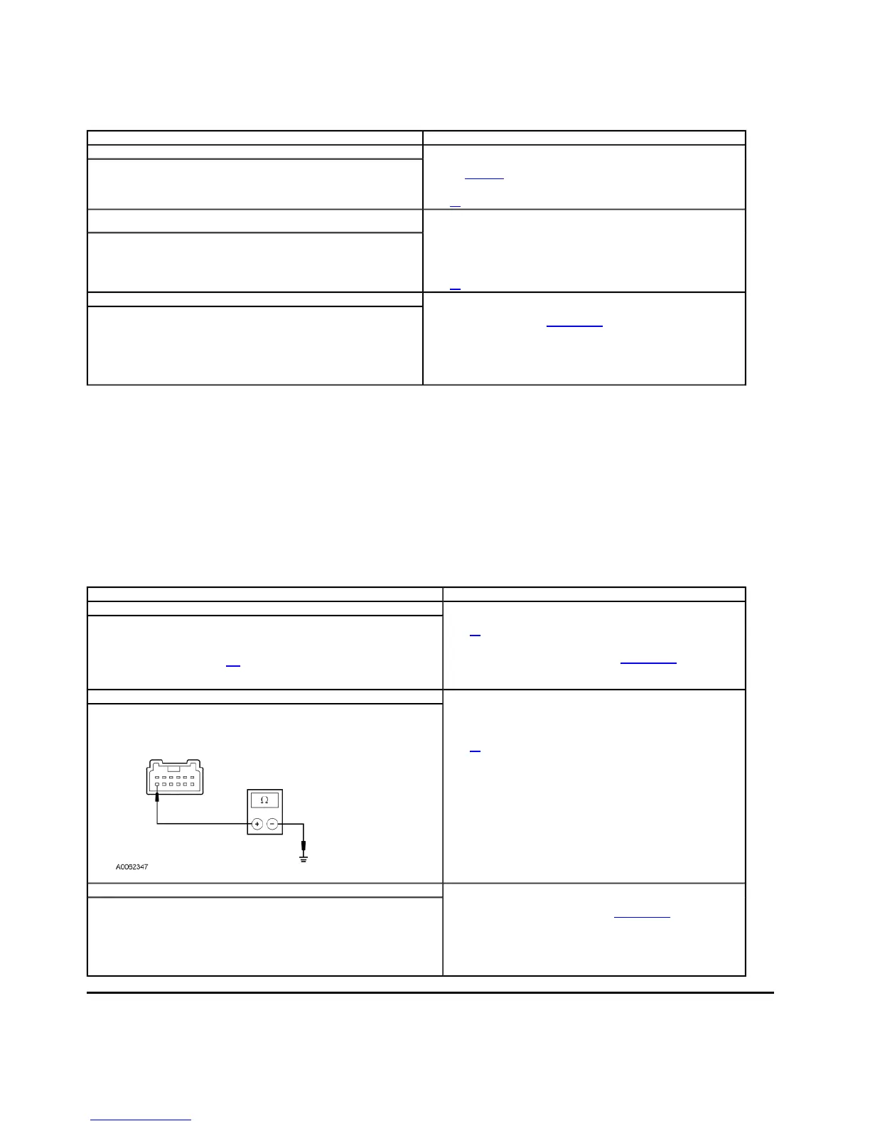
S2 CHECK CIRCUIT 8-LG43 (WH/VT) FOR SHORT TO GROUND
Disconnect: Instrument Cluster C220b.
Measure the resistance between the multifunction switch C202-7, circuit 8-LG43
(WH/VT), harness side and ground.
Is the resistance less than 5 ohms?
Yes
REPAIR the circuit. CLEAR the DTCs. TEST the system for normal operation.
No
GO to S3.
S3 CHECK FOR INSTRUMENT CLUSTER OPERATION
Ignition OFF.
Disconnect all instrument cluster connectors.
Check for:
corrosion
pushed-out pins
Connect all instrument cluster connectors and make sure they seat correctly.
Operate the system and verify the concern is still present.
Is the concern still present?
Yes
INSTALL a new instrument cluster. REFER to Section 413-00. TEST the system
for normal operation.
No
The system is operating correctly at this time. Concern may have been caused by
a loose or corroded connector. REPEAT the self-test.
2003 Thunderbird Workshop Manual
http://www.fordtechservice.dealerconnection.com/pubs/content/~WS3D/~MUS~LEN/19/S