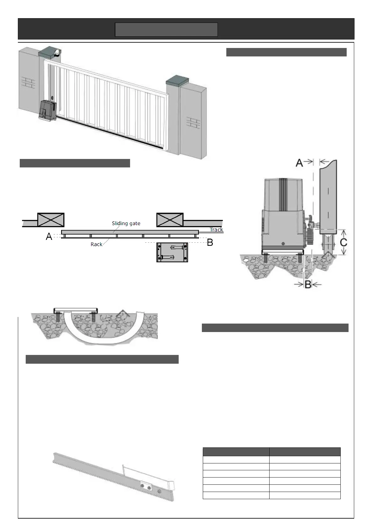
Mechanical
Gates must be level and free running on a ground
track, or on cantilever gate bearings. It is usual to
support the gate at the top with nylon rollers. Two
gates mounted on the same track may slide from
each side of an opening to meet in the centre.
The motor’s steel base plate is set in concrete at
the same time as the gate track. Their relative
height will depend on the size of the gate wheel
used, typically 80 – 100mm diameter.
The motor can be packed higher to meet the rack
if required. The toothed rack normally has slotted
mounting holes to allow accurate adjustment.
Mounting the motor and rack
Slotted holes in the motor base allow some adjustment. Mount
the motor square to the gate with the rack central to the pinion.
The toothed rack is best fitted using the motor pinion to set the
height. Make the fixing near the motor, then slide the gate along
to set next fixing height. Allow a 2mm gap between rack and
pinion to reduce drag and wear. This can be done by packing
the motor up by 2mm, then remove the packing later.
Skis are brackets bolted to the toothed rack to strike the motor
limit switches. Slide the gate to the open position. Set the ski so
that it bends the spring. Repeat for the closed position. Final
adjustment can be made when motor is running.
Alignment dimensions .
A Allow 25mm from the face of the gate to the back of the toothed rack.
B Allow 30mm from the centre the toothed rack to the edge of the base plate.
C Allow a min 92mm from underside of the base plate to bottom of toothed rack.
For wheels bigger than 100mm diameter, it may be necessary to cast the base plate into
a raised concrete plinth. If not, the base plate can be bolted to a ground level concrete
pad incorporating the ground track. We recommend fixing studding with resin because
the motor’s high shear force and vibration is inclined to loosen expansion bolts. Always
use washers and self locking nuts.
Ducts & Cabling
When casting the foundations, be sure to provide one or more
cable ducts to the underside of the motor base. It will not be
possible to run cables above the gate’s ground track. While
installing the ground track, it is useful to run another duct or
direct burial cable under the track to the opposite gate post.
Align the ducts with the fifth hole in the base plate. Cables
will be required for mains supply, photo beams and any
access control devices, for example an intercom. The motor
has two cable glands in the base for the cables.
At minimum, you will need a low voltage cable to each gate
post, and a mains supply to the motor base. The cable type
will depend on the duct standard. An eight core outdoor
grade alarm cable is adequate. More than one device at the
same location can be run from one cable using the universal
wiring scheme.
2 core + Earth, typ. 1.5mm²
2 core + Earth, typ. 0.75mm²
Skis fixing viewed from the motor side
 Loading...