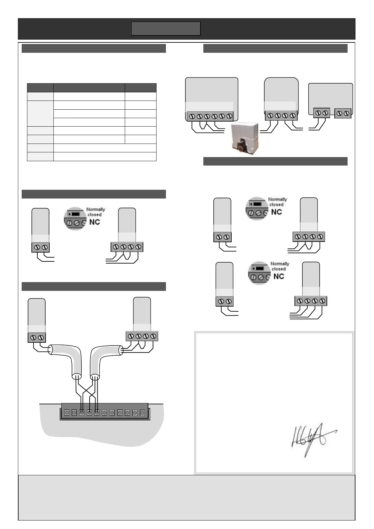
Universal wiring scheme
Following a standard wiring scheme simplifies wiring while
allowing additions in the future. For PICO we recommend an
8 core alarm cable with the following allocation.
Switched accessory supply
Audio2 or pedestrian input or safety link
Audio1 or lock or DC lamp
Run a cable to each location, or from one device to the next
in a chain. Connect to the device according to the table
below. The PICO also has the benefit of wireless devices.
FA31 Photo-beam (single set)
Make sure the link on the FA31 Rx is set to NC as shown.
PICO set wiring
Minimum wiring requires only
the FA31 photo-beam below.
Run an 8 core cable to each
side. For clarity, only the cores
used have been shown.
To left post To right post
Further devices can be
added to either cable.
E.g. vehicle sensor, exit
button, intercom, keypad.
R200 Intercom
This 2 wire intercom follows the universal wiring scheme.
Wire the power supply to the house phone (P+ & P-).
FA31 Photo-beam (double set)
The wiring is different for two photo-beams. In this scheme
the two blue wires are joined together in the control panel.
Make sure the link on both FA31 Rx is set to NC as shown.
Forematic
9 Vanalloys Estate
Stoke Row
Henley RG9 5QW www.forematic.com QPB05-F550
WARRANTY
3 year return to base warranty covers defective manufacture and material. The warranty does not
cover accidental damage, misuse, or abnormal wear. Warranty is conditional on good installation,
maintenance and service recommended in this manual. Warranty is void if subject of unauthorised
modification or repair, or abnormal input voltage. This does not affect your statutory rights
C-202 panel
L+ L- Go Go D/O D/O
Stop Gnd
Gnd
Door
SW2
SW1
Sync
Gnd
IR
IR 24
Lamp
24V
-Orange
-Black
-Green
-Black
-Yellow
-White
-Red
Declaration of Conformity
We hereby declare, that gate openers F-550 has been manufactured
in accordance with the following standards or normative documents
EN 60335-2-95: 2004
EN 60335-1/A13: 2008/A2: 2006
EN 62233: 2008
EN 61000-3-2: 2006, + A1: 2009 +A2: 2009
EN 61000-3-3: 2008
EN 55014-1: 2006 +A1: 2009 EN 55014-2: 1997 +A2: 2008
EN 50371: 2002
In accordance with the provisions of the following directives
98/37/EC Machinery Directive with amending directives
2006/95/EC LV Directive
2004/108/EEC EMC Directive
1999/5/EC R&TTE Directive
23.03.2011 – FOREMATIC
9 Vanalloys Estate, Stoke Row, Mr H WYNN JONES
Henley RG9 5QW, United Kingdom Director
 Loading...