Forma Scientific, Inc.________________________________________Routine Maintenance
8-2
• Layout test grids (refer to Section 8.4).
• Start-up the cabinet and allow it to run for at least twenty minutes.
• Take airflow measurements. If airflow specifications are not sufficient, open the
control panel and check the voltage on the power switch.
Note: Airflow measurements and voltages are recorded at the factory with the
cabinet connected to the appropriate AC power supply.
• Remove the access panel (Figure 4-1) and locate the blower motor circuit board.
(Figure 4-3) Using a true RMS Voltmeter, measure and record the voltage drop across
the white and black wires leading to the terminal strip. (Figure 4-4) The blower speed
control adjustment pot is located on the lower right side of the board. Clockwise
adjustment of this pot increases voltage supply to the blower motor, counterclockwise
adjustment lowers the voltage. Adjust it 2-3 volts, up or down, depending upon the
airflow required. Retake the airflow measurements.
If it is determined that the damper must be adjusted in order for the proper
airflow balance to be maintained, adjust it as follows.
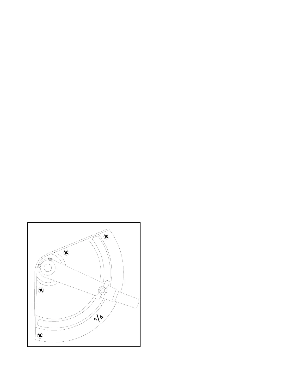
• The damper control (Figure 8-1 below) is located on the top of the cabinet.
• Loosen the wing nut, move the lever to the desired position, and retighten the wing nut.
Figure 8-1
O
P
E
N
I
½
¾
I
S
H
U
T
 Loading...