PN 153-231-B www.formfactor.com ACP40-GSG-xxx Probes • 1
Quick Reference Guide
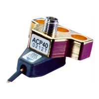
ACP40-GSG-xxx Probes
The ACP40-GSG-xxx probe features include:
• Standard Pitch: 100, 125, 150, 200 and 250μm
• 40 GHz Ground-Signal-Ground footprint microwave probe with Air Coplanar tip and 2.92mm
(K™ compatible) precision coaxial connector
XXX defines the pitch (center-to-center spacing between adjacent probe fingers).
Your calibration kit coefficient definitions are found on the inside of the probe box lid.
Probe Handling/Installation
Before mounting, inspect the probe for signs of dirt or visible wear. Use a
positioner with a standard 3-pin microwave mount. Use the middle (guide)
pin to align the probe and two mounting screws to snug-tighten the probe
(use 9/64 Contact Substrate (PN 005-018) to planarize the probe using the
positioner planarization adjustment.
Use high-performance microwave cable with 2.92mm (K™ compatible)
connectors.
When connecting RF connectors, carefully mate the connectors and tighten them by rotating only the male connector nut.
Use an 8 in-lb calibrated torque wrench to tighten the connectors.
Use the positioner cable clamp to relieve cable strain on the probe. Do not overtighten the clamp.
When unused, always cover the probe precision connector with the plastic cap supplied with the probe.
Probe Viewing
Always observe the probe tips when making the contact with the DUT. With the microscope focused
on the DUT and the probe tips safely raised, the probe tips appear out of focus.
Use the x- and y-axis knobs to position the probe tip above the DUT contacts. Use the z-axis knob to
bring the probe tips down to the device.
Before making contact, make sure that the probe station chuck is in the contact position and that the
platen arm is fully down.
When contacting a device, watch the probe tips through the microscope. Do not use electrical
readout as a substitute for microscope viewing. Observe contact and skating, then look for electrical readout.
Positioner Arm Planarization
The probe tip itself is planarized with high precision. However, it may still be
necessary to planarize the positioner arm to conform the probe tip plane to the
plane of the device being probed.
CAUTION
Use care when installing or handling the probe. Do not touch, bump or snag the probe tip.
Do not bend or flex the microwave absorber.
!
Cable clamp
Positioner arm planarization
adjustment knob