FortiGate-3000 and FortiGate-3600 FortiOS 3.0MR4 Install Guide
18 01-30004-0270-20070215
Powering on the FortiGate unit Installing the FortiGate unit
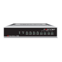
After a few seconds, SYSTEM STARTING appears on the LCD.
The main menu setting appears on the LCD when the system is running.
The FortiGate unit starts and the Power LEDs light up.
Table 3: LED indicators
Menu [ Fortigat -> ]
NAT, Standalone
LED State Description
Power Green The FortiGate unit is powered on.
Off The FortiGate unit is powered off.
1, 2, 3, 4,
4/HA, 5/HA,
INT, EXT
Green The correct cable is in use, and the connected equipment has
power.
Flashing
green
Network activity at this interface.
Off No link established.
1, 2, 3
(Interfaces)
(10/100
Interface)
Green The correct cable is in use, and the connected equipment has
power.
Flashing
Green
Network activity at this interface.
Green The interface is connected at 100 Mbps.
Off No link established.
Internal
External
(gigabit copper
Interfaces)
4/HA
(Interface)
Amber The correct cable is in use, and the connected equipment has
power.
Flashing
amber
Network activity at this interface.
Green The interface is connected at 1000 Mbps.
Off No link established.
Note: If only one power supply is connected, an audible alarm sounds to indicate a failed
power supply. Press the red alarm cancel button on the rear panel next to the power supply
to stop the alarm.
 Loading...