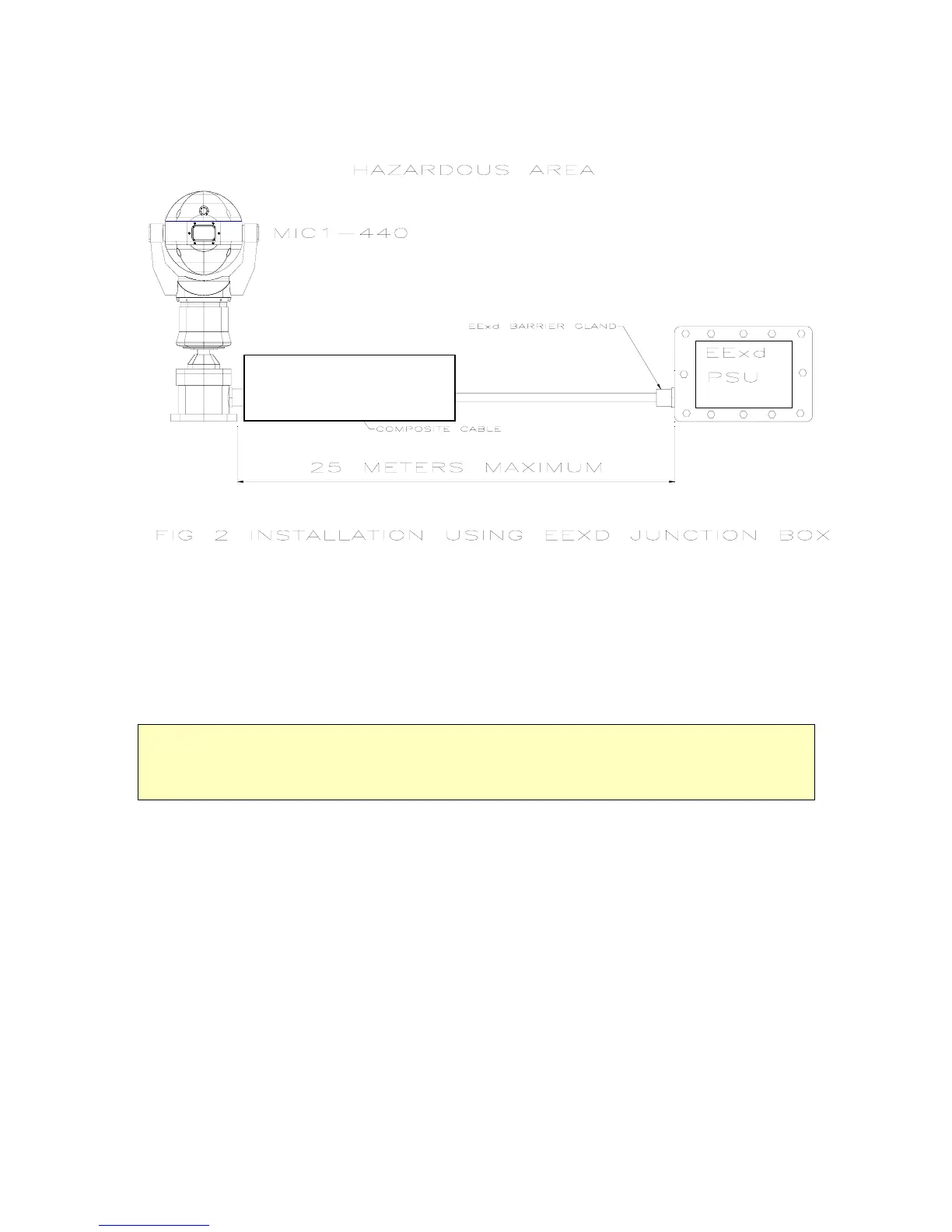
If it is not possible to fit the power supply in a non-hazardous area within 25 meters of the
MIC unit the Power supply will be fitted in a suitably rated EExd junction box (see fig 2).
Hawke 501/453 UNIV Size 0 for
armoured Cable
Hawke 501/421 Size 0 for Non-
armoured Cable
The MIC-440 is designed as a plug and play unit and it is highly recommended that the
connecting cable be fitted to the unit before installing the unit on site.
See Appendix E for more detailed installation diagrams defining cables and glands to
use.
Unpacking the camera.
L Take care when removing the unit from the packaging to ensure that the unit does not roll off the
working surface (on to your feet!).
Check that the packaging included the following parts:
MIC-440
12 Way cable connector.
EExd Barrier Gland of correct size and rating to match cable selected..
C.D. Containing installation instruction manual and CAMSET software
Installation in workshop
The unit is supplied with its internal connector and a suitable sized EExd barrier gland to
match the composite cable dia.
Examples of glands :
For FV Standard 8mm Dia Cable a Hawke 501/421 Size 0 provided.
For FV Armoured Cable 16mm Dia a Hawke 501/453 UNIV Size 0.
The cable is required to connect the MIC-440 to its power source, control data and video.
This composite cable consists of two pairs (24AWG) plus 4 cores (22 AWG), 2 Cores (24
AWG) and one coax cable for the video signal.
MIC1-440 Instruction Manual Page 6 of 43 Issue 2

 Loading...