8
VM200
3. SOFTWARE UPDATE
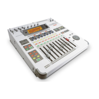
In order to update the VM200 software, the ROM CARD PCB (P/N:
8274219000) must be required. Mount the updated software (2 pcs.
EPROMs) into the EPROM sockets (U1 and U2) on the PCB. When
updating the software, make sure that the switch SW1 on the ROM CARD
PCB is set to “EPROM” side.
3-1. Preparation
3-2. Procedures
Turn the data wheel and select the menu “004 Program_Flash_ROM”.
Press the ENTER key. The VM200 starts transferring the program data
from the EPROM into the flash ROM on the MAIN PCB. The following
is the LCD display while updating the software inside the flash ROM.
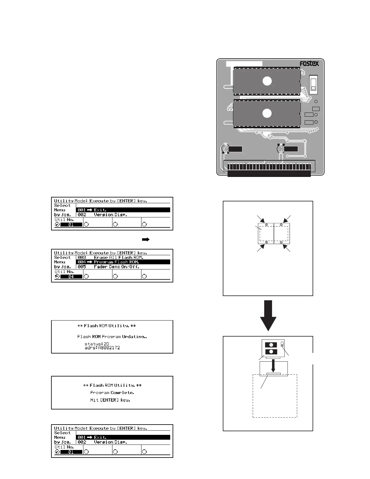
Loosen 4 x screws (BBT3 x 8 BZn) and remove 2 pcs. ROM Cover (P/N:
8221142000) on the VM200 bottom panel.
1)
Plug the ROM CARD PCB into the J18 connector on the MAIN PCB
Assy. When plugging the ROM CARD PCB, check if the EPROMs are
facing the bottom side.
2)
Turn on the power of VM200. On condition that the ROM CARD PCB
is correctly plugged in, the LCD display indicates the following.
3)
4)
After transferring the software is completed, the following is displayed
on the LCD display.
Press the ENTER key. The following is displayed on the LCD display.5)
8251984 001
U2
C9
1
J1
49
2
50
C8
EPROM
FLASH
SW1
TP2
NMI
TP1
TP3
U1
/RST
DGND
M27C2001
-10F1
M27C2001
-10F1
ROM CARD PCB TOP VIEW
SME
16V
10uF
SME
16V
10uF
(M)85˚C (M)85˚
VM200 BOTTOM PANEL
FRONT side
REAR side
VM200 BOTTOM PANEL
MAIN PCB
FRONT side
REAR side
Connector J18
(50-pin)
ROM CARD
PCB
EPROM/FLASH
SW
ROM COVER
 Loading...