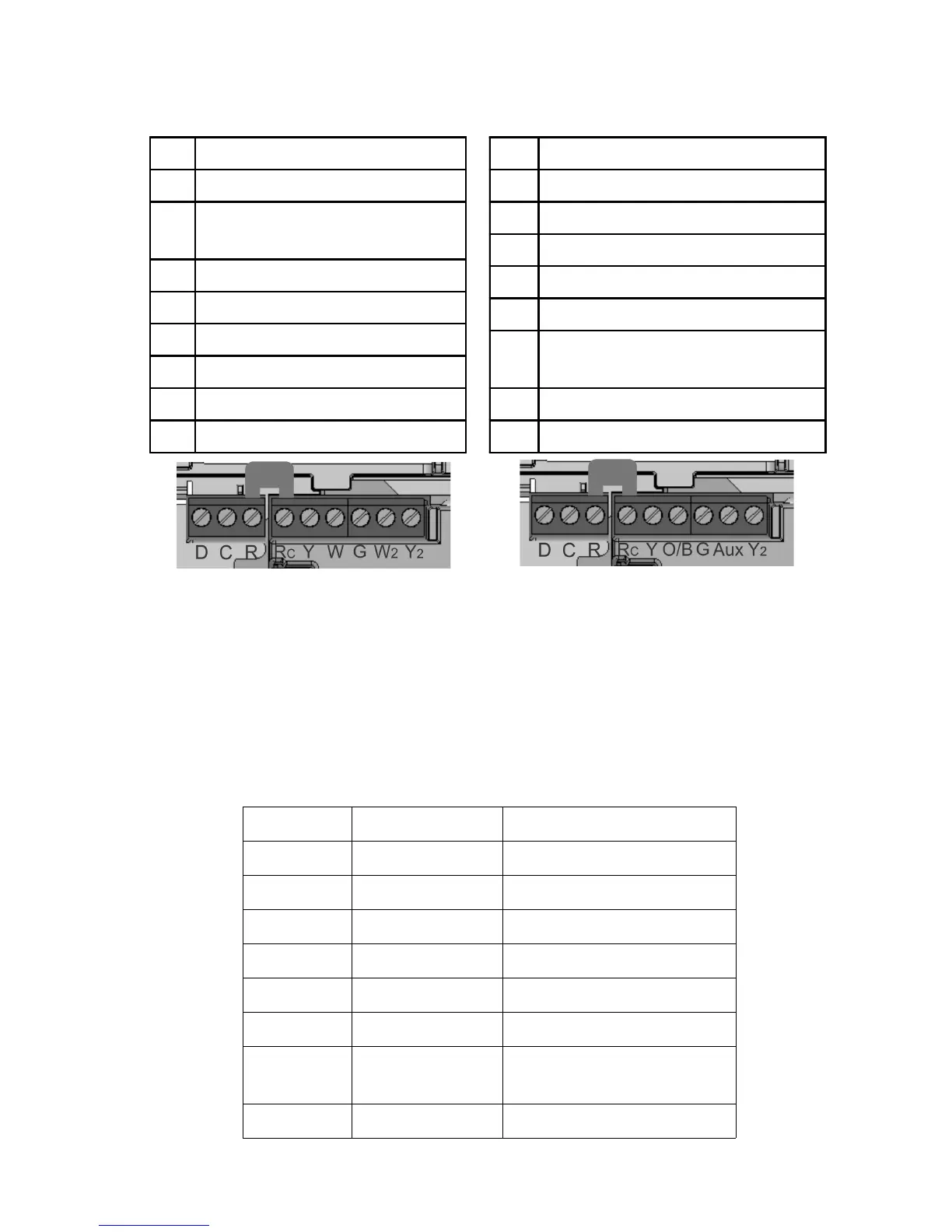
Terminal Designations
Conventional Heat Pump
R 24 VAC Power for Heat
Rc 24 VAC Power for Cool
C Common 24 VAC from
Heat Transformer
Y Cool Control – stage 1
W Heat Control – stage 1
G Fan Control
W2 Heat Control – stage 2
Y2 Cool Control – stage 2
D Data (Not Used)
R 24 VAC Power for Heat
Rc Jumper to Terminal “R”
C Common 24 VAC
Y Compressor – stage 1
O/B (W) Reversing Valve
G Fan Control
Aux (W2) Auxiliary/Emergency
Heat
Y2 Compressor – stage 2
D Data (Not Used)
Note: Remove jumper between R & Rc for two Transformer systems.
Standard Wire Colors
Most thermostat installations follow standard wire color designations.
This should be verified for your installation. These standard colors
are:
Terminal Color Description
R, Rc Red 24 VAC Power
W White Heat Control
G Green Fan Control
Y Yellow Cool Control
C Black 24 VAC Common
Y2 Blue or Orange Cool Control - Stage 2
W2 Varies Heat Control – Stage 2
Aux Varies, blue,
pink, gray, tan
Auxiliary or Emergency
Heat
O/B Varies, Orange Reversing Value
2