Frama F-Link Frama F-Link Frama F-Link
654
The unit has been preconfigured for integration using a network cable with DHCP. For the integration of the unit over
Wi-Fi, please refer to the Configuration Guide to see how to set the necessary parameters for Wi-Fi access.
3.1.2.1. Integration into the network using the network cable
Follow the steps listed below to connect the F-Link a/b or serial to your network with the network cable:
1. Connect one end of the supplied network cable with the RJ-45 network jack (LAN) on the F-Link.
Please refer to Fig. 6.
2. Connect the other end of the supplied network cable with an open RJ-45 port to your network
device.
3.1.2.2. Integration into the network using Wi-Fi
Follow the steps listed below to connect the F-Link a/b or serial to your network using a wireless link:
1. Attach the supplied Wi-Fi antenna to the F-Link as shown in Fig. 5. Move the antenna into a
vertical position.
2. Download the F-Link Configuration Guide from www.frama.com.
3. Supply power as described in the next section.
4. Configure the parameters as necessary.
3.2 Supplying power
Danger!
1.Before setting up the unit, check it for external damage. Commissioning a damaged
unit can be life-threatening.
2.A damaged connection cable may be replaced only with the identical type.
3.Each time you install the system, first check the cables and plugs, in particular at the
plug-in power adapter. Have damage repaired only by an electrical specialist.
4.Insert the mains plug into a socket only when the franking machine‘s housing is
closed.
5.Always run all cables away from the back of the unit and make sure there is no risk
of them being damaged or someone tripping over them.
6.Never remove the power plug from its socket by pulling on the power cord.
7.Keep children away from the unit.
8.Have repairs to the unit carried out only by Frama or an authorised Frama distributor.
Never open the unit yourself under any circumstances! Repairs done improperly can
result in considerable danger to the operator.
First re-establish the network connection for the franking system and turn it on.
Now connect the F-Link to the plug-in power adapter (power supply connection in Fig. 6). Afterwards, plug the power
adapter into a suitable mains socket. Turn on the F-Link using the On/Off switch (see Fig. 6).
The F-Link booting process (power-on process) takes approximately 2 minutes. Afterwards, the READY LED
lights up. The unit is now ready to use.
3.3. Establishing the initial connection with FramaOnline2
Note!
When establishing the initial connection between the F-Link and FramaOnline2, various
data is exchanged and, if necessary, software updates (firmware updates) are perfor-
med. Thus the initial connection can take as long as 5 minutes! Please note that
during a simultaneous new installa-tion of the franking system, the second connection
to FramaOnline2 can likewise take as long as 5 minutes!
Before establishing the initial connection to FramaOnline2, inspect the system (see the User Guide for your franking
system).
In case of a firmware update, the following message appears on the franking system‘s display:
F-Link Status: F008
F-Link is loading rmware!
Do NOT turn the F-Link off!
Wait until the READY LED
Light comes on, then
try again.
Wait until the READY LED lights up again (see the next section). Do not turn
the F-Link off! This process can take up to 5 minutes!
When the READY LED light comes on again, perform a second inspection.
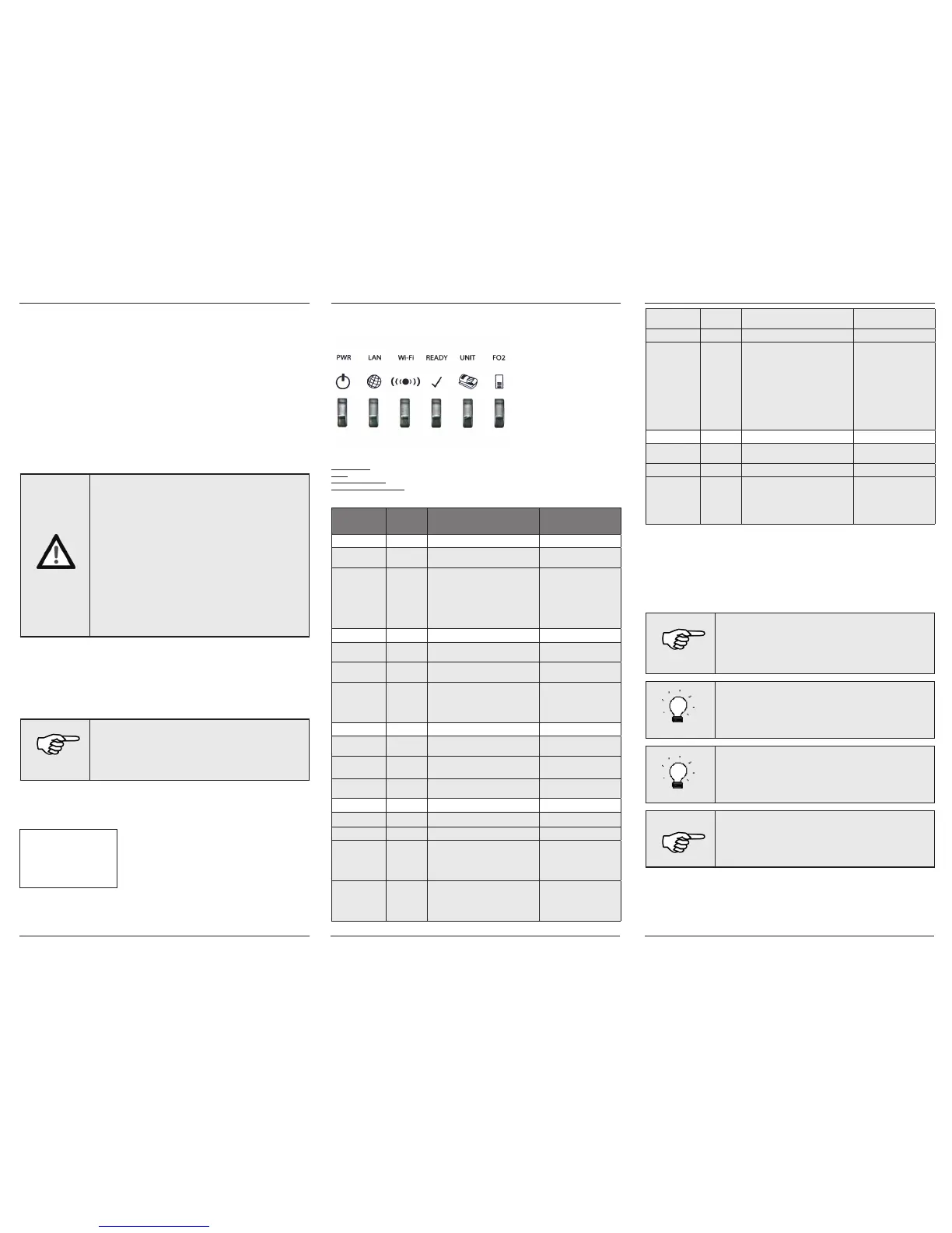
4. Control lamps and their meaning
The F-Link has six control LEDs. This section describes their meaning.
In the table below, the columns have the following meanings:
LED description: Information about the LED description
Status: The various possible LED status states
Meaning of the status: Meaning of the LED status for F-Link operation
Notes in case of a malfunction Detailed information in case of a malfunction
LED
description
Status Meaning of the status Notes in case of a mal-
function
PWR On The F-Link is connected to power and
turned ON
Off The F-Link is not connected to power or
turned OFF
If this LED does not light up,
check the connec-tion of the
plug-in power adapter to the
unit and that the adapter is
connected properly to the
mains. Press the ON/OFF
switch on the back of the
unit (Fig. 6).
LAN On The F-Link is successfully connected to
the LAN
Blinking The F-Link is sending/receiving data over
the LAN
Off The F-Link is not connected to the LAN If this LED does not light up,
check the net-work cable
and the connection as well
as the network device at the
other end.
Wi-Fi On** The Wi-Fi function of the F-Link is
turned on
Blinking The F-Link is sending/receiving data
over Wi-Fi
Off The Wi-Fi function of the F-Link is
turned off
READY On The F-Link is ready for operation
Blinking F-Link is starting...
Blinking* The F-Link is updating its firmware Wait until the LED again
lights up constant before
you re-establish a connection
between the franking system
and FramaOnline2.
Off The F-Link is not ready for operation Turn off the F-Link. Wait 10
seconds and turn the F-Link
on again. If the malfunction
continues, get in touch with
Technical Support.
UNIT On Data transfer between the F-Link and the
franking system is active
Blinking* The F-Link is updating its firmware
Off No data transfer between the F-Link and
the franking system.
The LED is turned on only
if there is a connec-tion to
the FramaOnline2 server and
indicates that the connection
between the franking system
and the F-Link has been esta-
blished. If this LED does not
light up, check the connec-
tions. Review Section 3 and
the figures on Page 2 once
again in detail and compare
the connections.
FO2 On Data transfer between the F-Link and
FramaOnline2 is active
Blinking* The F-Link is updating its firmware
Off No data transfer between the F-Link and
FramaOnline2
In case of a malfunction, a
message appears on the dis-
play of your franking system.
This mes-sage is described in
more detail in the Configu-ra-
tion Guide.
* If the READY, UNIT and FO2 LEDs are all blinking at the same time, the F-Link is updating its firmware. Do NOT turn
the F-Link off when in this state!
** To use Wi-Fi, switch on the Wi-Fi function of the F-Link and configure the Wi-Fi parameters according to the infor-
mation in the Configuration Guide. The Wi-Fi LED does NOT indicate if the F-Link has successfully established a wireless
link to an access point! Instead, check the status of the F-Link in the browser interface.
5. Fault messages
In case of a malfunction, the F-Link unit issues a message on the display of your franking system. During the initial
installation, messages always appear in English.
Note!
You can find more detailed information about configuring the unit using the integra-
ted browser interface by reading the Configuration Guide, which can be downloaded
at www.frama.com.
That guide contains the current status list with notes about troubleshooting and
debugging.
Tip!
The F-Link‘s permanent IP address is: 192.168.1.200. In case of a malfunction, the
F-Link‘s dynami-cally assigned IP address appears on the franking system‘s display.
After resetting the F-Link, issuing a dynamic IP address using DHCP is always activated.
Tip!
The address for FramaOnline2 is: fo2.frama.com.
Note!
In case of a firmware update for the unit (status: F008), the unit may not be disconnec-
ted from the network under any circumstances. This could result in damage. Wait until
the READY LED lights up constant before you disconnect the unit from the network or
re-establish a connection with
FramaOnline2.
For status messages that indicate an invalid or modified configuration setting, the F-Link IP address is always displayed.
Enter the IP address in the address line of your browser to access the F-Link configura-tion menu.
The Configuration Guide (download from frama.com) contains the current status list with notes about troubleshooting.
 Loading...