0415 2000102902
1
A. INSPECTION
Inspect the carton and water cooler for evidence of rough handling and concealed damage. Damage claims should be filed
with carrier.
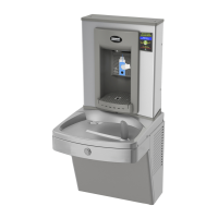
B. TO PUT WATER COOLER AND FOUNTAIN INTO SERVICE
1. NOTE: Provincial and local plumbing codes may prohibit use of saddle taping valves for water line connection in some applica-
tions. All connections must conform to applicable plumbing codes.
2. Locate and install plumbing and electrical service if required, in accordance with the Rough-in Drawing. Filter units have
additional instructions on a label inside the access panel. Read these before installing unit.
3. FLUSH BUILDING WATER SUPPLY LINE BEFORE INSTALLING UNIT.
4. Install unit on the wall hanger. Wall hanger is shipped fastened to the back of the unit.
5. Install a trap in the waste line and a shut off valve in the water supply line. An in-line strainer is furnished in the “Water Sup-
ply” tube. Connect the “Water Supply” tube to the shut off valve. This connection should not be a solder joint or flare connection
to allow access to the strainer for service. To ease removal of the strainer, a sheet metal screw may be lightly threaded into the
open end. When the unit has an internal waste trap, the trap should be wrapped with the insulating tape to prevent sweating. Use
of the 1 3/4" diameter knockout for a waste line is not recommended because of a potential conflict with ADA* toe space clear-
ance requirements. Check your local building code inspector for approval.
6. Rotate the fan blade by hand to see that it is free of obstructions.
7. Check the available power supply against the water cooler data plate to assure the correct electrical service. Plug power supply
cord into wall outlet. The rear most 1 3/8" diameter knockout in the frame bottom is for an externally located electrical supply.
Make sure the knockout hold edge is smooth and free of any burrs. Use of a Heyco bushing #2184 in the knocked out hole is
recommended in order to prevent damage to the service cord and to close up excess opening around the cord. Route the cord so
it does not interfere with ADA* space requirements.
8. To fill cold water tank on water cooler versions, open water supply line shut-off and push any one of the front or side
pushbuttons to allow water to flow to the bubbler. On the EE model, actuate the solenoid by holding one hand approximately 3"
from the infrared sensor. Run water until stream free of bubbles.
9. To Adjust Bubbler:
a) All Pushbutton models are equipped with a Cartridge Regulator. The KEP8AC and KEPAC have a slot in the shelf below the
Pushbuttons. Insert a screwdriver in the slot to adjust regulator. Turn adjustment clockwise to increase stream height. To ac-
cess the KEPV8AC adjustment, remove the Bezel and Button from the front of the cooler.
b) Electric Eye (EE) models have a Regulator built into the the Bubbler. If adjustment is needed, insert a 5/64" wrench approxi-
mately 1 1/8" into the bubbler nozzle opening until it bottoms out and is seated in an adjust screw. Turn the adjust screw
clockwise to reduce stream height or counter clockwise to increase the height. Note: less than one turn is required to go from
a closed to a wide open flow. Do not over tighten the adjuster in the closed position as stripping the hex impression in the
adjust screw may result. Turn the adjuster 1/16 of a turn at a time.
10. On electic eye equipped models, place and then hold hand approximately 3" from the sensor to actuate the solenoid valve.
After approximately 30 seconds run time, the sensor will automatically shut off the solenoid valve. To reactivate, move hand away
for an instant and then again place it in front of the sensor.
DRINKING FOUNTAIN INSTALLATION
For All Universal KEP( )AC Series Drinking Fountains