EasyManua.ls Logo

Freedom 25 User Manual

Default Icon
40 pages
To Next Page IconTo Next Page
Page #1 background imageLoading...
Page #1 background image
Part No. 90-0113-00
Fdmman2.p65 2/98
OWNER’S MANUAL
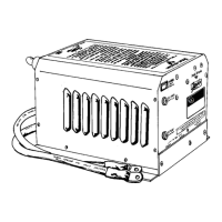
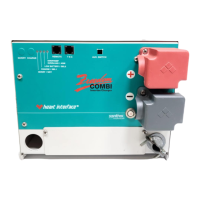
FREEDOM COMBI
TM
INVERTER/CHARGERS
FREEDOM MODELS 10, 15, 20, 25
®
A Valley Forge Company
UL

Questions and Answers:

Freedom 25 Specifications

General IconGeneral
CoolingFan-cooled
Output Voltage12V/24V DC
Output Current25A
Battery Type CompatibilityLithium
Protection FeaturesOver-voltage, over-current, short-circuit, reverse polarity, over-temperature

Summary

SAFETY SUMMARY

General Safety Information

General safety information for installation and operation is contained throughout the manual.

Definitions of Warnings

Warning statements identify conditions or practices that could result in personal injury or equipment damage.

Fuse Replacement Guidelines

Replace fuses only with specified voltage, current, and type ratings for fire protection.

Power Source Voltage Requirements

Operate equipment within specified AC (line) and DC (battery) voltages to avoid damage.

Servicing Safety Precautions

Do not open the unit; refer all servicing to qualified personnel for safety.

INTRODUCTION

DC to AC Power Inverting

Describes the function of converting DC power to AC power for appliances.

Automatic Transfer Switching

Automatic switching between inverter power and incoming AC power.

3-Stage Battery Charging

Details the three-stage process for charging batteries automatically.

Electronic Protection Features

Outlines the unit's protection against overloads, short circuits, and temperature issues.

THINGS YOU SHOULD KNOW

Circuit Breaker Protection

Explains the circuit breakers protecting the inverter/charger and input circuits.

Thermostat Controlled Cooling

Describes the fan system that cools the unit for continuous operation.

Inverter Idle Circuit Operation

Automatic energy saving feature that reduces power consumption when no load is present.

Low and High Battery Protection

Details automatic shutdown at low or high battery voltage levels.

Power Sharing Feature

Feature that automatically reduces charger consumption to allow power to loads.

REMOTE CONTROL PANELS

Freedom Remote Control Panel

Optional panel providing system status, battery voltage, and current via LED bargraphs.

Link Instrumentation Options

Advanced remote panels (Link 1000, 2000, 2000R) for control and status monitoring.

OPERATION

Power Switch Functionality

Controls ON/OFF and RESET for the inverter; functions independently of external AC power.

Inverter Overload Protection

Describes how overload protection, transfer switching, and charging regulation operate automatically.

BATTERIES

Battery Types and Selection

Recommends deep-cycle batteries (wet cell, gel cell, AGM) and advises against car batteries.

Battery Interconnection

Explains series and parallel connection methods for battery banks.

Battery Bank Ratings and Sizing

Guidelines for calculating battery bank size based on Amp-hour ratings and discharge cycles.

Power Consumption Formulas and Chart

Formulas to calculate DC Amp-hour draw for 12 Volt systems based on AC loads.

BATTERY CHARGING

Charging Fundamentals

Explains charging needs for wet cell batteries and limitations of conventional chargers.

Freedom Charger Stages

Highlights the 3-stage charging process (Bulk, Acceptance, Float) for optimal recharging.

Equalizing Charge and Over-Discharged Batteries

Details equalizing charge benefits and procedures for charging severely depleted batteries.

Battery Charging Warnings

Lists crucial warnings for performing the equalizing charge safely and effectively.

BATTERY CHARGER VOLTAGE SETTINGS

Voltage Settings Table

Table detailing bulk, float, and equalize voltages for different battery types and temperatures.

INSTALLATION PRECAUTIONS

Ignition Protection and Flammability

Equipment is not ignition protected; avoid installing near batteries or flammable materials.

Ground Fault Circuit Interrupter (GFCI) Usage

Use only GFCI receptacles for continued protection against electric shock.

Corrosion and Moisture Prevention

Avoid mounting where exposed to rain, dripping, or spray to prevent failure.

Ventilation Requirements

Do not obstruct ventilation openings to prevent overheating.

Electrical Shock Hazard: Servicing

Both AC & DC voltage sources are terminated inside; open each circuit before servicing.

Required Tools and Accessories

Lists common tools and essential accessories for a complete installation process.

INSTALLATION

Key Installation Points and Warnings

Critical pre-installation steps like turning off the power switch and avoiding backfeed.

Mounting, Clearance, and Wiring Generalities

Guidelines for unit mounting, clearance, battery cable length, and connecting systems.

Grounding and Neutral Bonding

Procedures for connecting the chassis to AC ground and understanding neutral bonding.

AC Input/Output Wiring and Options

Instructions for AC wiring, connecting to input/output pigtails, and model-specific input configurations.

AC Output, GFCI, and Remote Wiring

Connecting AC output, GFCI receptacle recommendations, and remote control cable routing.

DC Wiring and Battery Cable Fusing

Guidelines for DC wiring, warnings against reverse polarity, and battery cable fusing requirements.

Recommended Fuse Types and Assembly

Lists recommended fuse types and illustrates correct fuse assembly stack-up.

Pre-Start Up Checks and Testing

Essential pre-power checks and step-by-step testing for inverter, transfer, and charger functions.

Battery Charger Function Test

Steps to verify the battery charger is operating correctly after installation.

TROUBLESHOOTING

Common Inverter and Charger Issues

Addresses issues like no inverter output, low voltage, charger output problems, and slow cooking.

REMOTE CONTROL PANEL ADDENDUM

Panel Features and Indicators

Details remote power switch, status LEDs, and DC Volts/Amps bargraph indicators.

REMOTE CONTROL PANEL

Dip Switch Functions

Explains the function of dip switches for manual equalizing and battery type settings.

Advanced Dip Switch Settings

Covers settings for auto charge, idle sensitivity, and power sharing.

Dip Switch Status and Wiring

How to check dip switch positions and instructions for remote control wiring.

REMOTE CONTROL PANEL STATUS LEDs

LED Status and Purpose

Detailed explanation of each status LED and its purpose in inverter/charger modes.

REMOTE CONTROL PANEL

DIP SWITCH PROGRAMMING Chart

Comprehensive chart detailing dip switch functions and settings for various features.

TROUBLESHOOTING WITH THE FREEDOM REMOTE CONTROL PANEL DC AMPS BARGRAPH

Overload LED Troubleshooting

Chart correlating overload LED numbers to specific fault conditions and troubleshooting steps.

GLOSSARY

Technical Terms A-D

Defines Alternating Current (AC), Amps, Ampere-hour, AGM, AWG, Circuits, Combi, Current, Cycle, Dip Switch, DC.

Technical Terms E-W

Defines Equalize Charge, Gel Cell Battery, GFCI, Ground, LED, NEC, Negative, Ohm, Positive, Power Sharing, Volt, Watt, Wet Cell Battery.

SPECIFICATIONS

Model Specifications Overview

Comprehensive table detailing specifications for Freedom 10, 20, and 25 models.

Freedom 15 Model Specifications

Table listing detailed specifications for the Freedom 15 model.

WARRANTY

Warranty Terms and Service Information

Details limited warranty period, registration, service contact, and return authorization.

Related product manuals