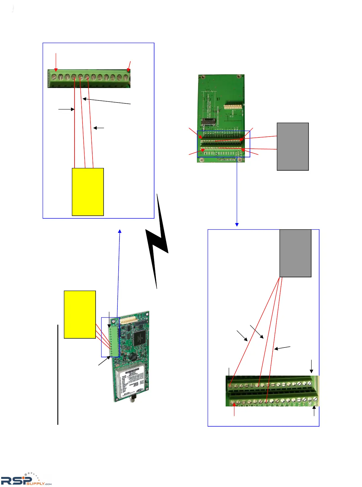
FGRIO Wiring Diagram
1-5 V Pressure
or Temperature
Sensor
A 3 wire connection is
made from Sensor to
IO Slave
Terminal Block of
IO Slave
1-5 V Pressure
or Temperature
Sensor
Sensor Ground Wire connects to
screw terminal # 9 Ground.
Sensor Power Wire connects to screw
terminal # 7 VSNS.
Sensor Output Wire connects to screw
terminal # 8 Analog Input 1.
RTU
A 2 wire connection for
analog output is made from
FGRIO Master to the RTU.
Sensor Power should also
be connected if available.
RTU
Analog Output wire connects from
Analog Output 1 screw terminal to
Analog Input of the RTU
Terminal Block of
FGRIO Master
Ground wire connects
from Ground screw termi-
nal to Ground on the RTU
IO Slave transmits analog
and digital signals over air
to FGRIO Master.
Sensor Power Output connects from
Sensor Power screw terminal to Sensor
Power Output of RTU.
Screw Terminal # 12
Screw
Terminal #12
Screw
Terminal
#1
GND
Sensor
Power
GND Sensor Power
Not
Used
B+
Not
Used
B+
Screw Terminal # 1
http://www.RSPSupply.com/p-20028-FreeWave-FGR2-IO-IOE-Radio-Enclosed-900-MHz-I/O-Slave-Radio.aspx
 Loading...