Brake Chamber Stroke Specifications
Chamber
Max Applied Stroke: inch (mm)
Manufacturer Type
*
Size
†
Meritor
Standard Stroke
9
Less than 1-1/2 (38)
12
16
Less than 1-3/4 (44)
20
24 Less than 1-7/8 (48)
Long Stroke 24
Less than 2 (51)
Standard Stroke 30
*
Long stroke design is indicated by a tag, or embossing, on the brake chamber.
†
Specifications are relative to a brake application with 80 to 90 psi (550 to 620 kPa) air pressure in the brake chambers.
Table 3, Brake Chamber Stroke Specifications
42–13 Versajust Slack Adjuster
Inspection and
Lubrication
IMPORTANT: Perform the Brake Inspection
maintenance operation before lubricating the
slack adjusters.
1. Visually check for physical damage, such as bro-
ken air lines and broken or missing parts.
2. Using a quality multipurpose chassis lubricant,
NLGI Grade 2, lubricate the slack adjuster
through the grease fitting until clean lubricant
flows from the grease relief opening in the boot.
3. Perform the "In Service Inspection."
In Service Inspection
1. Apply and release the brakes several times while
observing the slack adjuster. The slack adjuster
and brake actuator should move freely, without
binding or interference, and should return to the
full released position. Observe the looseness that
exists between the clevis and adapter bushing
and the yoke and link pins and their mating parts
(clevis, body, link). Replace these parts if loose-
ness appears excessive. Make certain the brake
actuator pushrod jam nut is tightened securely.
2. Inspect the slack adjuster for physical damage,
paying attention to the link, boot, and clevis. If
any components are damaged, repair or replace
them as necessary.
3. Measure the brake actuator pushrod stroke while
making an 80 to 90 psi (552 to 621 kPa) brake
application. Actuator pushrod strokes should not
exceed the values shown in
Table 4 and
Table 5. To achieve the correct pressure for this
test, build the system pressure up to a 100 psi
(690 kPa). Shut down the engine. Fan the
brakes to attain a 90 to 95 psi (621 to 655 kPa)
reading. Make and hold a full brake application
while the strokes are checked.
03/02/2004
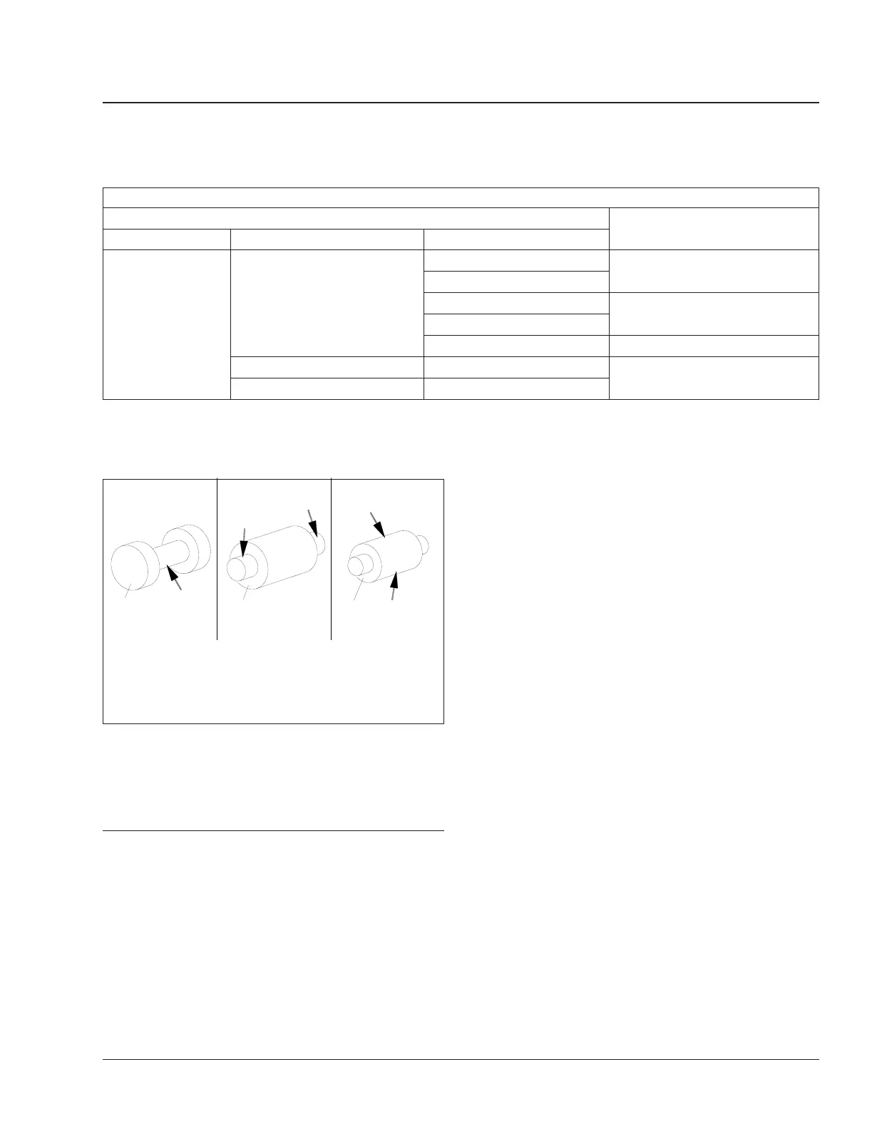
1
2
3
f430370
1. Cam Roller Pin Lube Point (Q Series)
2. Cam Roller Pin Lube Points (Q, Q Plus, and P
Series)
3. Cam Anchor Pin Lube Points (Q, Q Plus, and P
Series)
Fig. 12, Cam and Anchor Roller Pin Lubrication Points
Brakes 42
Recreational Vehicle Chassis Maintenance Manual, July 2018 42/13
 Loading...