Do you have a question about the Friedrich FRESHAIRE PVH09K3FA and is the answer not in the manual?
General safety warnings and hazard types to be aware of during operation and maintenance.
Guides for interpreting unit model and serial numbers for identification and service.
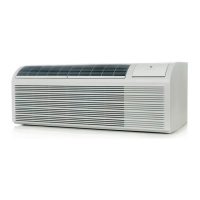
Overview of the unit's key features, benefits, and technological advancements.
Detailed performance, airflow, and physical data for 9-12k heat pump models.
Information on voltage, amperage, power cords, and wiring specifications.
Explanation of buttons, display, and basic operational modes like cooling and heating.
Details on DIP switch settings, advanced parameters, and protection functions.
Explanation of the refrigeration cycle, including diagrams and principles.
Covers cleaning coils, chassis, filters, fan motors, and wall sleeves.
Guidelines for proper unit placement and minimum installation clearances.
Detailed steps for mounting the wall sleeve and installing the drain system.
Methods for different wall types, grille, and chassis installation.
Instructions for connecting remote thermostats and desk controls.
Steps to ensure proper installation and initial operation.
Steps for safely removing the main unit chassis and control panel.
Procedures for replacing PCBs, power cord, and IPM.
Steps to remove and replace blower wheels and motors.
Procedures for replacing heating elements and fresh air components.
Steps to replace the outdoor fan and reversing valve solenoid.
Key safety and handling precautions for working with R-410A refrigerant.
Procedures for charging, undercharging, overcharging, and restrictions.
Standard procedure for system charging and repairs using the weigh method.
Testing capillary tubes and the reversing cycle check valve.
Description, testing, and replacement procedures for the reversing valve.
General checks, overload tests, and detailed replacement procedures.
Procedures for testing indoor/outdoor fan motors and capacitors.
Diagrams showing main and power PCB connector functions.
Common malfunctions and their corresponding solutions.
Table of error codes, meanings, and troubleshooting steps.
Flowchart for diagnosing power-related issues and unit startup failures.
Testing heater coils and troubleshooting the electric heater control circuit.
Procedures for testing thermistors and reference resistance values.
Guide to using the parts catalog for identifying and ordering components.
Visual breakdown of unit components with corresponding part numbers.
Descriptions of accessories for installation, such as subbases and duct adapters.
Conversion chart for temperature units, providing Fahrenheit and Celsius equivalents.
| Model | PVH09K3FA |
|---|---|
| Cooling Capacity (BTU) | 9000 |
| Voltage (V) | 115 |
| Smart Features | No |
| Ventilation | Yes |
| Refrigerant | R410A |