48 PB
UNIT DISASSEMBLY AND COMPONENT REPLACEMENT
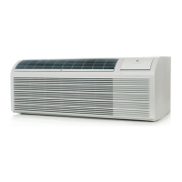
Open Electrical Control Box
1. Remove front panel (Figure 501).
2. Remove User Interface (Figures 502 thru 504).
3. Remove 7 screws.(Figure 505)
4. Unhinge electrical box.
1. Remove front panel (Figure 501).
2. Remove User Interface (Figures 502 thru 504).
3. Open electrical Control Box (Figure 505).
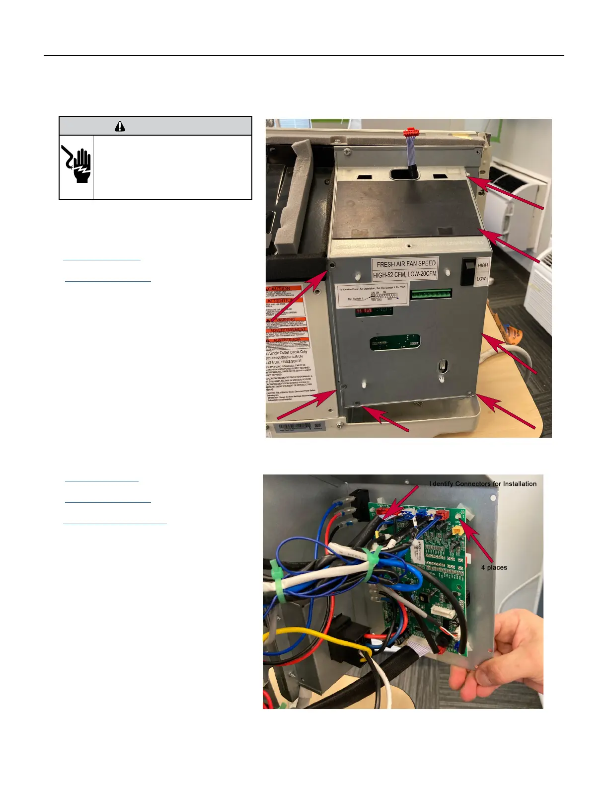
4. Snip wire ties to loosen wire bundles. (Figure
506).
NOTE: It is a good practice to take pictures
of the wiring connections to facilitate
reinsallation.
2. Disconnect wire connectors from Main PCB (logic)
board one at a time. Identify plugs for reinstallation.
3. Remove 4 standoffs by pinching tip and applying
slight upwards pressure to the board.
Remove Main PCB (logic) Board
Figure 505 (Open Electrical Box)
Figure 506 (Remove Main PCB (logic board)
WARNING
ELECTRIC SHOCK HAZARD
Turn off electric power before service or
installation. Extreme care must be used, if it
becomes necessary to work on equipment with
power applied.
Failure to do so could result in serious injury or
death.
 Loading...