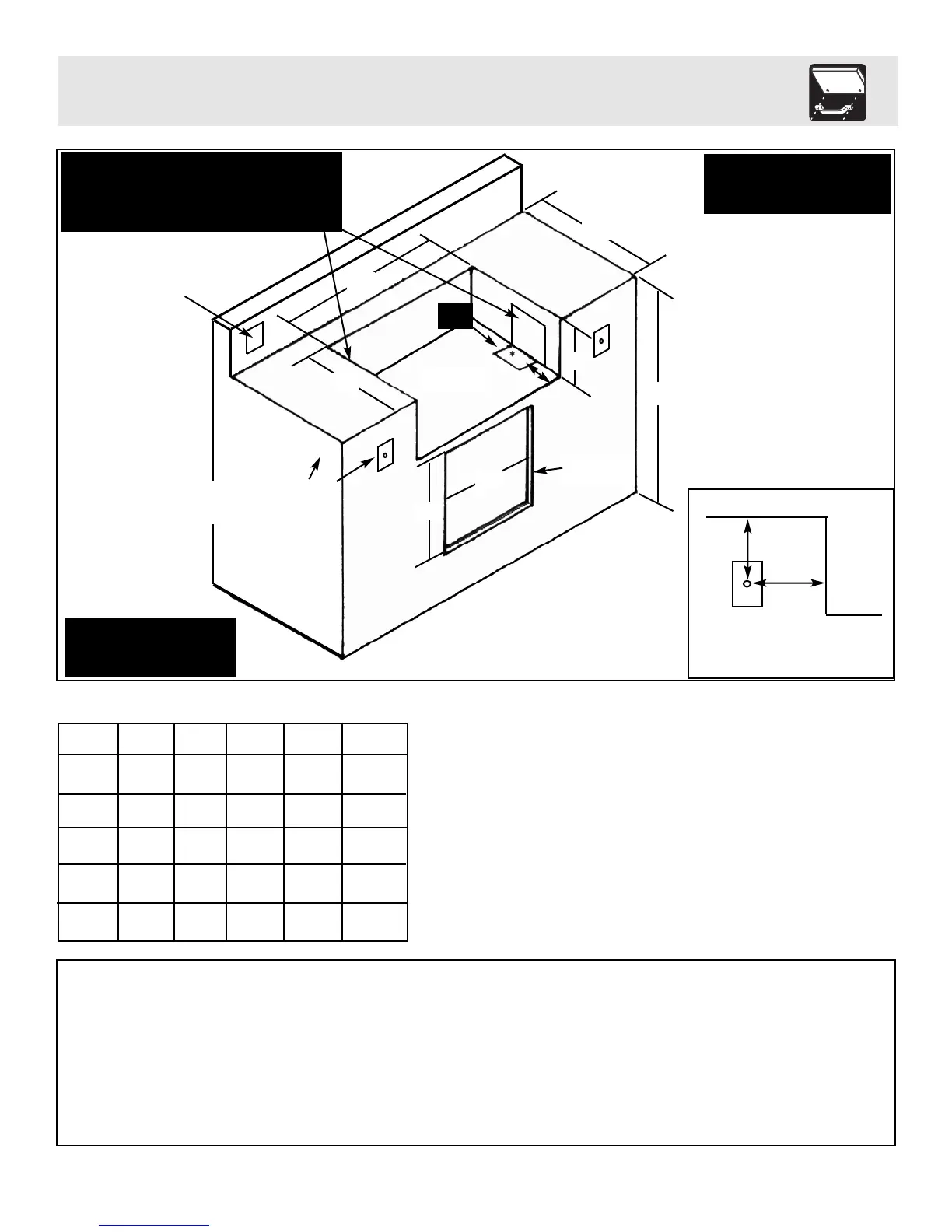
Built-In Instructions
8
35
1
/
2
” Max.
2
7
1
/
2
”
Min.
B
D
E
C
*Gas
Cutout
2”
Opening for
access door(s)
A
B
C
D
E
51”
Grill
51
1
/
8
”
20
7
/
8
”
13
1
/
16
”
N/A
N/A
44”
Grill
44
1
/
8
”
20
7
/
8
”
13
1
/
16
”
N/A
N/A
57”
Grill
57
1
/
8
”
25
1
/
4
”
13
1
/
16
”
N/A
N/A
Single
Access
Door
N/A
N/A
N/A
18
1
/
4
”
18
1
/
2
”
Dual
Access Door
N/A
N/A
N/A
36
1
/
8
”
18
1
/
2
”
Additional Requirements:
*Gas connection cut out in floor support needs to be 4” wide x 6” long, set 6” back from front edge.
*Ignitor cutout is equal to a standard electrical outlet with a minimum depth of 2
1
/
2
”.
*If using a backsplash apron or rear wall, locate electrical service on the left hand side for rotisserie motor connection.
*A minimum clearance of 12” from the back must be maintained between the grill and any combustible construction such as wood
siding of a residence, 3” minimum for non-combustible construction.
3”- 5”
3”- 5”
Grill
Maximum distance to center of
ignitor button from side of gril
l
IGNITOR PLATE
INSTALLATION
Side cutouts are needed on each side to feed ignitor
w
ires to the ignitor plates and allow access to side gas
connections
(Size: 10” high x 5” long, set 1” back from front edge)
A
G
FI Electrical outlet
for rotisserie motor
(6.5 amp min.)
Built-in dimensions
Floor Support
area for grill
Note: Make sure to use a
non-combustible base and
s
ides for the structure
*A minimum 3” clearance is
required between the back of the
grill hood and a non-combustible
surface.
counter top
*Required Ignitor cutout
for front or side mount

 Loading...