For questions, please call 1-800-672-4399.
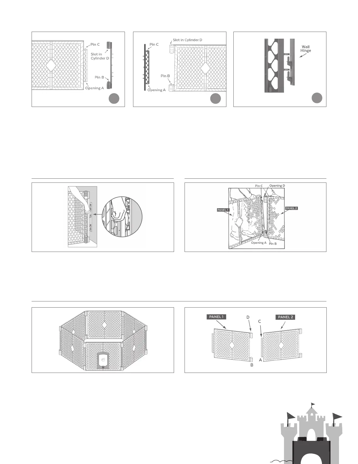
REMOVAL FROM WALL HINGE TO DISCONNECT PANELS
INSTALLATION AS A FREESTANDING ENCLOSURE
STEP 4 Attach the mounting connector
side A to panel 1 by setting opening A over
Pin B, push down in order to slide Pin C
into the slot of Cylinder D. See Figure 6.
To remove the gate from the wall hinge, press on the locking
boss located on the center of the wall hinge (See Figure 9), and
lift the panel itself until the gate rib clears the locking boss.
To disconnect two adjoining panels, select one of the joints where
the panel pushes down (panel 1), as shown in Figure 10. Gently
press down on panel 1 while lifting slightly on panel 2. This will
enable you to slide Pin C free of Cylinder D (see Figure 10). Then
lift up on panel 1 until Opening A (see Figure 10) is free of Pin B.
Begin setting up your enclosure by unsnapping the gray carrying strap and carefully unfolding the panels to form a hexagon. See
Figure 11. When you have finished unfolding the panels, there will be two unconnected panels arranged as shown in Figure 12.
Make certain that the pin in Cylinder B is up as shown. Begin connecting the panels together by gently lifting up on panel 2 and
setting the Opening A (as shown in Figure 12) over Pin B located on panel 1.
Now locate the slot on the lower end of Cylinder D. See Figure 12. This slot tapers to an opening that
accommodates Pin C. Gently press down on panel 2 while aligning Pin C with the slot in Cylinder D.
While maintaining downward pressure on panel 2, lift slightly on panel 1, and slide Pin C through the
slot and into the opening as shown.
STEP 5 Attach the mounting connector
side B to panel 2 by setting opening A
over Pin B, push down in order to slide
Pin C into the slot of Cylinder D. See
Figure 7.
STEP 6 Attach the mounting connectors,
that are now attached to the panels, to
the wall hinges by aligning the horseshoe
shaped hoops on one side of the gate over
the pins on the wall hinges to set the gate
in place. See Figure 8. NOTE: Always lift up
on the end panels to ensure that the gate is
properly secured and locked in place.
54
6
FIGURE 6
FIGURE 11
FIGURE 9
FIGURE 12
FIGURE 10
FIGURE 7 FIGURE 8
 Loading...