14 Optional Equipment
5WPMAN0148 (Rev. 5/16/2008)
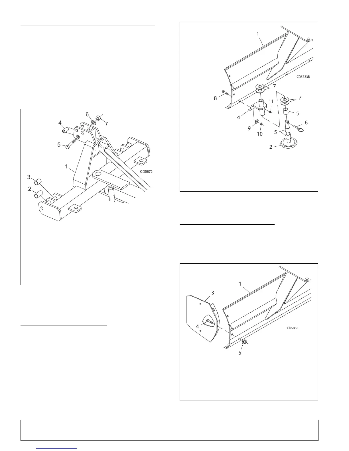
QUICK HITCH BUSHING KIT 5WP1002011
NOTICE
Do not use Quick Hitch with Single Tailwheel
Kit.
Install cap screw (5), sleeve (4), lock washer (6), and
hex nut (7) through bottom hole of A-frame as shown.
Install sleeves (2) for Category 2 tractors in outer pin
locations. Install sleeves (3) for Category 1 tractors in
inner pin locations as shown.
Figure 13. Quick Hitch Bushing Installation
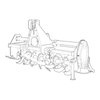
SKID SHOE KIT 5WP18300 (Figure 14)
Remove plow bolts from each end of cutting edge.
Attach right and left skid shoe brackets (3 & 4) to rear
of moldboard with plow bolts (8), washers (9), and lock
nuts (10) supplied in kit. Top of skid shoe brackets
should angle slightly toward outer edge of blade.
Adjust skid shoe to desired height using washers (7)
and spacers (5). One washer must be installed
between the shoe bracket and the spacers.
Make sure skid shoe rotates freely to prevent prema-
ture skid pad wear.
Figure 14. Skid Shoe Installation
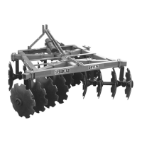
END PLATE KIT 5WP1001531 (Figure 15)
Install one end plate to each end of rear blade using
two carriage bolts (4) and flanged lock nuts (5) on each
end plate.
Figure 15. End Plate Installation
1. A-Frame assembly
2. Sleeve, .94 x 1.44 x 2.75 Cat 2
3. Sleeve, .94 x 1.44 x 2.19 Cat 1
4. Sleeve, 1.0 x 1.25 x 2.06
5. 1.0 NC x 5.0 Cap screw GR5
6. 1.0 Lock washer
7. 1.0 NC Hex nut
1. Moldboard assembly
2. Skid & shaft assembly
3. Right skid shoe bracket
(not shown)
4. Left skid shoe
bracket
5. Spacer, 1-1/4
sch 80 x 3/4" pipe
6. Pin, Klik 7/16 x 2"
7. 1-1/4" Standard flat washer
8. Plow bolt, 5/8 NC x 2-1/2"
9. 5/8" Standard flat washer
10. 5/8" NC Hex lock nut
11. Grease fitting
1. Moldboard assembly
2. End plate (right, not shown)
3. End plate (left)
4. 1/2 NC x 1-1/4" Carriage bolt
5. 1/2 NC Flanged lock nut