Do you have a question about the Frost Fighter IDF350-II and is the answer not in the manual?
Detailed technical specifications for IDF350-II and IDF500 models, including input, nozzle size, and electrical supply.
Specifies the maximum allowable duct lengths for IDF 350 and IDF 500 models based on discharge outlet configuration.
Provides recommended minimum clearances for heater installation around top, sides, burner, and discharge ends.
Guidelines for connecting the flue pipe, including vertical section length and horizontal run rise ratio requirements.
Step-by-step instructions for starting the heater using Honeywell or Genisys controls and how to properly shut it down.
Troubleshooting steps for when the heater fails to start and procedures for handling oil accumulation in the combustion chamber.
Covers checks for high limit switch, fan switch, fuel filter, flame detector, burner, electrical connections, fan, and motors.
Detailed steps for removing and cleaning the heat exchanger and combustion chamber components.
Guidance on adjusting combustion air for optimal efficiency using air band and shutter settings.
Information on adjusting temperature feelers and fan switches for optimal performance in different ambient temperatures.
Details on setting electrode spacing and slide plate adjustments for IDF350-II and IDF500 models.
Identification of key components within the heater's junction box, including controllers and breakers.
Procedure for setting the 'Z' dimension on the nozzle line assembly for IDF350-II and IDF500 models.
Troubleshooting steps for issues like no power, unit not firing, or burner starting but not igniting.
Addresses problems such as burner lockouts, smoky fires, and delayed ignition sequences.
Guidance for troubleshooting fan not coming on, cycling on high limit, or combustion chamber turning red.
Describes the sequence of operation for the Honeywell R7184B primary control, including standby and lockout states.
Explains the sequence of operation for the Genisys controller, covering burner states and safety features.
An exploded view identifying key parts of the IDF350-II and IDF500 with part numbers.
Overview of primary controls used on OHV heaters, including White Rogers and Honeywell models.
Wiring diagrams for IDF350-II/500 models with both Honeywell and Genisys control systems.
Detailed view of the burner electrode assembly and the 'A' pump, including connection ports.
Identification of heat exchanger components, including outer shell, combustion chamber, and flue collar.
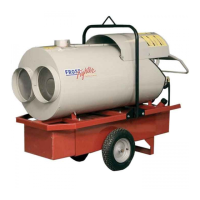
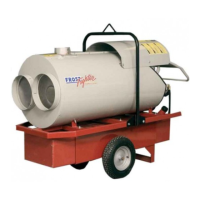
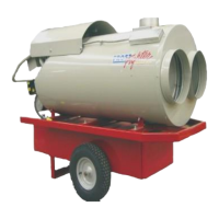
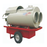
Visual identification of external components from the front and back views of the IDF350/500 units.
Instructions for slide plate and electrode adjustments specific to OHV models.
Overview of limit switches, adjustable fan switches, and temperature feelers used in the heaters.
| Brand | Frost Fighter |
|---|---|
| Model | IDF350-II |
| Category | Heater |
| Language | English |