Do you have a question about the Frosty Factory 137 and is the answer not in the manual?
Explains the manual's purpose, notation, and how to use it effectively.
Guides on unpacking, checking for shipping damage, and verifying included accessories.
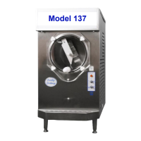
Detailed labels identifying each part of the machine for easy reference.
Provides precise measurements and required space around the unit for operation.
Emphasizes understanding safety warnings before operation and servicing.
Covers optimal placement, ventilation, and correct electrical hookup procedures.
Details the operation modes controlled by the front panel selector switches.
Advises on mix sugar content, fruit juices, and alcohol for proper freezing.
Explains using the TCC screw to fine-tune product consistency.
Step-by-step guide to filling the hopper and initiating the freezing process.
Factors influencing freeze time and expected durations.
Outlines essential cleaning for exterior, parts, and faucet assembly.
Procedure for cleaning the air-cooled condenser to ensure optimal performance.
Instructions for lubricating and installing the beater shaft and seal assembly.
Steps for correctly reattaching the faceplate and its bushing.
Covers daily, weekly, and monthly maintenance for machine longevity.
Procedures for safe and effective long-term storage of the unit.
Lists and labels all components for the faceplate and faucet assembly.
Demonstrates correct application of Teflon tape to the faucet body.
Guides on fitting the plunger assembly and securing the main faceplate.
Explains the components and correct orientation for the float switch assembly.
Shows the electrical connections for the thermostat in stand-by mode.
Instructions for using the drip tube brush for thorough cleaning.
Method for cleaning the ceramic ring within the cylinder.
Guidance on lubricating the beater shaft and correctly installing the seal.
Emphasizes correct positioning of the carbon ring for proper sealing.
Step-by-step process for fitting the scraper blade and spring seal.
Steps for installing the beater bar and securing the faceplate.
Procedure for safely removing a faulty ceramic seal using the puller tool.
Detailed steps for applying sealant, inserting, and curing a new ceramic seal.
How to increase tension by repositioning the motor assembly.
Method for aligning the pulleys using an Allen screw for optimal belt performance.
Lists all individual parts that constitute the Franklin drive motor assembly.
Visual guide to checking for contact between the shaft and ceramic ring.
Illustrates the precise locations for inserting shims to achieve proper alignment.
Provides an exploded view and an itemized list of parts for the rear cylinder assembly.
Diagnoses for startup problems, motor operation, and freezing inconsistencies.
Solutions for dripping mix, loud noises, and incorrect product consistency.
Addresses issues with fill light, rocking motion, and blocked product flow.
Covers intermittent compressor, beater bar, and mix discoloration problems.
Lists essential replacement parts for the machine from A to F.
Lists remaining spare parts, covering faucet components to thermostats.
Illustrates the wiring diagram for the junction box, motor, and control switches.
Shows the interplay of contactor, timer, transformer, and switches in the control circuit.
Provides a detailed electrical drawing of the 137A model, illustrating all circuits.
Details the warranty coverage, exclusions, and requirements for service.
| Brand | Frosty Factory |
|---|---|
| Model | 137 |
| Category | Kitchen Utensil |
| Language | English |