9
INSTALACIÓN - HVDP-HR
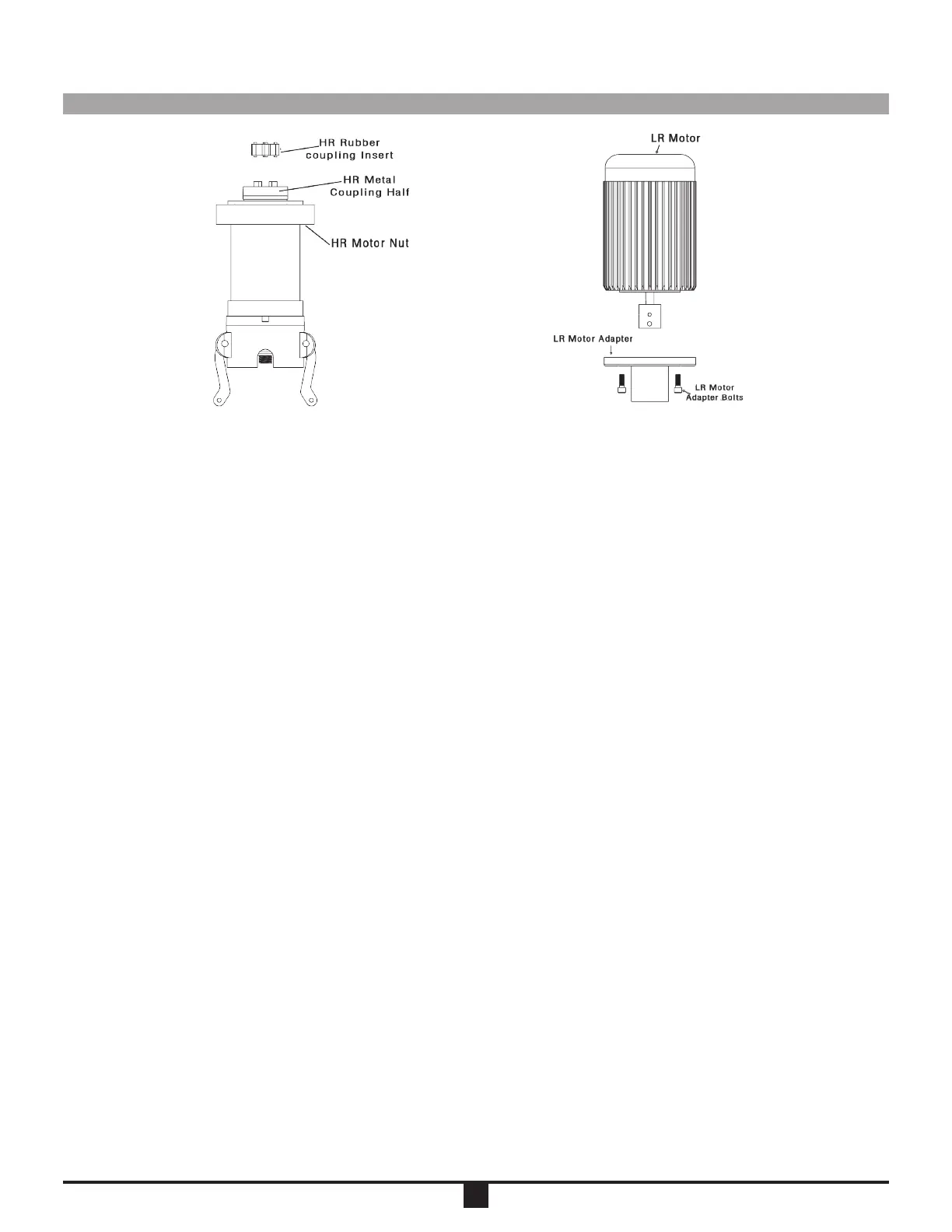
1. Localice el inserto de acoplamiento de goma que se envió
por separado en una bolsa de plástico (consulte la Figura
1).
2. Instale el inserto de acoplamiento de goma en la mitad de
acoplamiento de metal ubicada en la parte superior del
conjunto del impulsor HR.
3. Encuentre la mitad de acoplamiento de metal ubicada dentro
del motor HR. Alinee este acoplamiento con el inserto de
goma
Instalado en el segundo paso de estas instrucciones.
4. Deslice el motor HR en el conjunto del variador HR.
5. Apriete a mano la tuerca del motor en la punta roscada del
motor HR.
ELIMINACION - HVDP-HR
1. Para retirar el motor HR, invierta las instrucciones de insta-
lación del motor HR que se encuentran en esta sección.
INSTALACIÓN - HVDP-LR
1. Compruebe la dirección de rotación del motor LR (motores
de aire y de inducción) antes de instalar el motor en la
bomba.
ADVERTENCIA: La rotación del motor debe ser hacia la
derecha cuando se ve desde el extremo del ventilador del
motor. Si gira el motor en la dirección incorrecta, se dañará
la bomba.
2. Retire los pernos del adaptador del motor (consulte la Figura
2) y separe el adaptador del motor del motor.
3. Enrosque el adaptador del motor en el conjunto del variador
LR. Apretar a mano el adaptador del motor.
Nota: Los hilos son zurdos. Además, se recomienda usar lubri-
cante para roscas para garantizar un montaje suave y sin
ataduras.
INSTALLATION - HVDP-HR
1. Locate the rubber coupling insert that was separately
shipped in a plastic bag (see Figure 1).
2. Install the rubber coupling insert onto the metal coupling
half located on top of the HR drive assembly.
3. Find the metal coupling half located inside the HR motor.
Align this coupling with rubber insert
installed in the second step of these instructions.
4. Slide the HR motor onto the HR drive assembly.
5. Hand tighten the motor nut onto the threaded nose of the
HR motor.
REMOVAL - HVDP-HR
1. To remove the HR motor, reverse HR motor installation
instructions found in this section.
INSTALLATION - HVDP-LR
1. Check the rotation direction of the LR motor (air and induc-
tion motors) before installing the motor onto the pump.
WARNING: Motor rotation must be clockwise when
viewed from the fan end of the motor. Rotating the motor in
the wrong direction will cause damage to the pump.
2. Remove the motor adapter bolts (see Figure 2) and separate
the motor adapter from the motor.
3. Thread the motor adapter onto the LR drive assembly. Hand
tighten the motor adapter.
Note: Threads are left-handed. Also, thread lubricant is
recommended to ensure smooth, bind free assembly.
4. The LR motor coupling consists of two 5/16” diameter pins
welded to a hub. The LR drive assembly coupling has two
slots that receive these pins. Align the pins of the motor
coupling with the slots on the drive assembly coupling and
slide the motor onto the drive assembly.
Figure 1
(la Figura 1)
Figure 2
(la Figura 2)
INSTALLATION INSTALACIÓN


 To Next Page