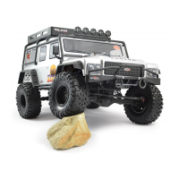
Do you have a question about the FTX Kanyon and is the answer not in the manual?
General safety guidelines and critical warnings for operating the RC vehicle.
List of necessary tools for assembly and upkeep of the vehicle.
Other components needed to operate the RC vehicle, like batteries.
Instructions on connecting the LED lights to the receiver for illumination.
Guidance on properly positioning and securing the RC transmitter aerial.
Steps for safely charging and installing the vehicle's battery pack.
Important guidelines for safe and effective battery use and care.
Overview of the Electronic Speed Controller's capabilities and technical details.
Visual guide for connecting ESC wires and initial setup procedures.
Explanation of different running modes and programmable protection options.
Important warnings, operational functions, and LED indicator meanings for the ESC.
Welcome, safety precautions, and service information for the radio system.
Guidelines for operating the transmitter and maintaining its batteries.
Procedures for charging the transmitter and its detailed technical specifications.
Identification of physical controls and features on the transmitter.
Detailed explanation of how to use the transmitter's controls for steering and throttle.
Step-by-step guide to wirelessly connect the receiver to the transmitter.
How to set up and understand the failsafe system for safety.
Steps to follow after operating the vehicle, including battery care.
Routine checks and maintenance tasks to keep the vehicle in good condition.
Exploded view of the shock absorber components and their assembly.
Exploded view of the front and rear gearbox components.
Exploded view of the rear axle assembly and its parts.
Exploded view of the front axle assembly and its components.
Exploded view of the steering mechanism components.
Exploded view of the main chassis frame and battery/receiver case parts.
Exploded view of the body mounting bracket components.
Exploded view of various linkage components.
Exploded view of the central differential lock mechanism parts.
Exploded view of the central transmission components.
Exploded view of the differential box components.
Exploded view of the motor and its mounting components.
Exploded view of the second central transmission assembly.
Exploded view of the assembled linkage system.
Exploded view of the central drive train components.
Exploded view of the shock absorber assembly on the chassis.
Exploded view of the wheel and tire components.
Exploded view of the first part of the vehicle body assembly.
Exploded view of the roll cage components.
Exploded view of the second part of the vehicle body assembly.
| Brand | FTX |
|---|---|
| Model | Kanyon |
| Category | Automobile Accessories |
| Language | English |