WWW.FUHR.PL
• Można stosować do elementów z tworzywa sztucznego,
drewna i aluminium.
• Skrzydło i rama muszą przebiegać na równolegle na tej
samej wysokości.
• Należy stosować wyłącznie wkładki profilowane zgodne
z DIN 18252.
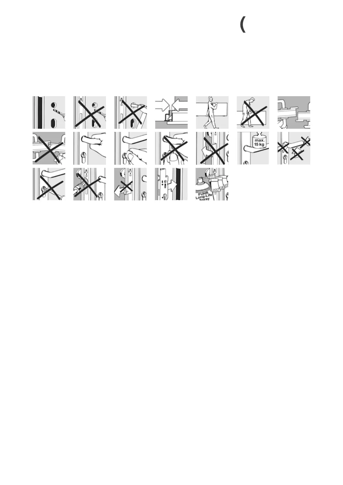
• Wyfrezowanie na skrzynkę zamka zgodnie z rysunkiem.
• Wyfrezowanie na wkładkę profilowaną i klamkę muszą być
dopasowane.
• Nigdy nie wiercić otworów na okucia przy wmontowanym
zamku.
• Przed montowaniem zamka należy usunąć wszystkie
zanieczyszczenia np. wióry z obszaru frezowania.
• Listwę czołową i zaczepy zamocować wkrętami ø 4 mm
o długości dopasowanej do systemu profili.
• Wkręty montażowe należy wkręcić prostopadle do listwy
czołowej.
• Zwrócić uwagę na dokładne umiejscowienie zaczepów
zgodnie z rysunkiem.
• Przy dokręcaniu wkrętów listwy czołowej zwrócić uwagę
na to, żeby pręty zasuwane mogły się swobodnie poruszać.
• Dla elementów plastikowych certyfikowanych przez SKG:
Listwę czołową i zaczepy połączyć przynajmniej dwoma
wkrętami (ø 4 mm) z profilem wzmacniającym.
• Dla elementów aluminiowych certyfikowanych przez SKG:
Listwę czołową i zaczepy zamocować wkrętami ø 4 mm
o długości dopasowanej do systemu profili do profilu
aluminiowego.
• Dla elementów drewnianych certyfikowanych przez SKG:
Listwę czołową i zaczepy zamocować wkrętami ø 4 mm
o długości 40 mm.
• W razie ewentualnych oporów w działaniu zamka po
montażu nigdy nie używać siły! Zamiast tego należy znaleźć
i usunąć przyczynę.
• Przy transporcie drzwi – również przy zamkniętym zamku
– chronić skrzydło przed przesunięciem.
Instrukcje montażu i zamocowania
Installation and fixing instructions
• Solely profile cylinders according to DIN 18252 have to be
installed.
• Applicable for elements made of PVC, timber or aluminium.
• Door leaves and frame must run in parallel throughout the
entire height.
• Mortise for the lock cases as per drawing.
• Mortise for the profile cylinder and lever must be in
alignment.
• Never drill the fitting when the lock has been installed.
• All contamination such as shavings as a result of drilling
must be removed prior to the installation of the lock.
• Attach faceplate and strike plates with screws of a 4 mm
diameter and a length matching the profile system.
• Fixing screws have to be positioned perpendicular to the
faceplate.
• Observe exact position of the strike plates as per drawing.
• Observe by fixing the faceplate screws that the rods must
have the room to move freely.
• For SKG-certified PVCu doors: Connect faceplate and
strike plates to the reinforcing profile with at least two
screws (ø 4 mm).
• For SKG-certified aluminium doors: Attach faceplate and
strike plates with the aluminium profile with screws of
a 4 mm diameter, length matching to the profile system.
• For SKG-certified timber doors: Attach faceplate and strike
plates with screws of a 4 mm diameter and 40 mm in
length.
• Do not use force in the event of tightness or sluggish
operation after the lock has been installed! The cause of the
problem should be ascertained and remedied instead.
• Suitable protection must be applied to the door leaves
during transportation even if the locks are bolted.
 Loading...