EasyManua.ls Logo

FUHR autotronic 834 - User Manual

FUHR autotronic 834
12 pages
Print Icon
To Next Page IconTo Next Page
Loading...
WWW.FUHR.DE
836
autotronic
834
autotronic
QSG15/DE-EN/03.21-14
QuickStartGuide
www.fuhr.de
autotronic 834/836
Standardfunktionen
Verriegeln (Schließen):
Beim Schließen der Tür fahren automatisch
zwei Fallenriegel (autotronic 834) bzw. zwei
Fallenbolzen-Schwenkriegel- Kombinationen (auto-
tronic 836) auf 20 mm aus. Diese und sind gegen
Zurückdrücken gesichert.
Durch Ausschließen des Mittenriegels über den
Zylinder wird der gesamte Verschluss mechanisch
gesichert. Jegliche Öffnungsmöglichkeiten über den
Motor sind damit deaktiviert. Gleichzeitig ist der In-
nendrücker zu Kontrollzwecken oder als Kindersi-
cherung gesperrt.
Entriegeln (Öffnen) von außen:
Mit dem Schlüssel des Zylinders
Optional über eine FUHR Funk-Zutrittskontrolle
oder jedes andere Zutrittskontrollsystem
Entriegeln (Öffnen) von innen:
Wie gewohnt über den Türdrücker oder mit dem
Schlüssel des Zylinders
Optional über eine Hausgegensprechanlage, ein
Zutrittskontrollsystem oder ein Gebäudemanage-
mentsystem
Weitere Anschlussmöglichkeiten
(einige nur mit Steuerung möglich)
Alarmanlagen
Zutrittskontrollsysteme
Elektrisch betätigte Drehtürantriebe
Zeitschaltuhren (Dauerentriegelung)
Externe Kontroll-LED
Elektronisches Abschaltsignal der Zutritts-
kontroll systeme für Alarmanlagen
autotronic 834/836
Standard functions
Locking (closing):
By closing the door, two latching deadbolts (auto-
tronic 834) or two latching and hook bolt combina-
tions (autotronic 836) extend automatically to 20
mm. Both are secured against being pushed back.
By triggering the central deadbolt via the cylinder,
the total locking system is mechanically secured. All
possibilities of opening by means of the drive unit
are deactivated.
At the same time the internal lever handle is blocked
for control purposes or as a child safety lock.
Unlocking (opening) from the outside:
By using the cylinder’s key
Optionally by means of a FUHR radio access
control or any other access control system
Unlocking (opening) from the inside:
As usual by the lever handle or by using the cylin-
der’s key
Optionally via an intercom system, an access
control system or a facility management system
Further connection possibilities
(some only possible with control unit)
Alarm systems
Access control systems
Electrically operated swing door drives
Time switches (permanent unlocking)
External indicator LED
Access control system’s electronic shut down
signal for alarm systems
Beachten Sie bitte ebenfalls die detaillierten
Informationen: www.fuhr.de
Handbuch Zusatz- Leistungs-
information erklärung
Please also note the detailed information:
www.fuhr.de
Manual Additional Declaration of
information performance
DE | EN
834P/836P 834P/836PFluchttüren
emergency exits834/836 834/836

Other manuals for FUHR autotronic 834

Question and Answer IconNeed help?

Do you have a question about the FUHR autotronic 834 and is the answer not in the manual?

Summary

autotronic 834;836 Standard Functions

Locking (Closing)

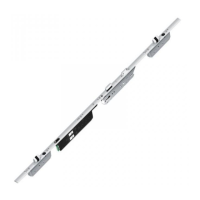
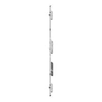
When closing the door, two latching deadbolts (autotronic 834) or two latching and hook bolt combinations (autotronic 836) extend automatically to 20 mm.

Unlocking (Opening) from the Outside

By using the cylinder's key; Optionally by means of a FUHR radio access control or any other access control system.

Unlocking (Opening) from the Inside

As usual by the lever handle or by using the cylinder's key; Optionally via an intercom system, an access control system or a facility management system.

Further Connection Possibilities

(some only possible with control unit)

Important Notes and Installation

Product Application and Liability

System designed for entrance doors; no liability for non-original parts or improper installation.

Environmental Protection

The multipoint locking system must be protected from humidity and chemical substances.

Emergency Access

Always carry a cylinder key for emergencies like power failure to ensure access.

Adjustment Options

Ensuring reliable function requires correct installation and adjustment of locks, hinges, and strike plates.

Installation Examples

Standard Installation - Cable Loop

Example of a standard installation with a cable loop and without control.

Standard Installation - Spring Contact

Example of a standard installation with a spring-loaded contact and without control.

Standard Installation - Frame Power Supply

Example of a standard installation with spring contact and frame-mounted power supply.

Standard Installation - All Inclusive

Example of a standard installation where all components are mounted within the door.

Project Installation - DIN Rail

Example of a project installation with spring contact and DIN rail components for a switch cabinet.

Project Installation - Control Box

Example of a project installation with spring contact and a control box.

Control with FUHR Radio Access Control Systems

Master Radio Key

Master radio key included with control unit/receiver; used for pairing additional keys and systems.

Master Key Security

Master key cannot be deleted or switched; must be kept safe as it is essential for managing other keys.

Key Battery Indicator

Radio keys feature a battery indicator light and are energy saving.

Key Pairing and Deleting

Description of how to pair and delete 4-channel radio keys for individual button assignment.

Control Units and Radio Receiver Module

Frame-Mounted Control Unit

Identification of the frame-mounted control unit and its programming button.

DIN Rail Control Unit

Identification of the DIN rail control unit and its programming button.

Permanent-Open Function - Wired

Enables a permanent-open function via an external or optional switch.

Permanent-Open Function - Wireless

Enables a permanent-open function via a radio key or other FUHR access control systems.

Radio Receiver Module

Identification of the radio receiver module and its LED programming button.

Pairing User Radio Keys (Max. 24)

Initial Key Deletion

For security, delete all radio keys before initial installation (refer to page 7).

Initiate Pairing Mode

Press the programming button briefly (max. 1 sec.) on the control unit or radio receiver module.

Confirm Master Key

Press the master key's front, centre button within 20 seconds to confirm.

Pair New Key

Press a button on the new radio key twice consecutively within 20 seconds.

Pair Additional Keys

Repeat the pairing process from step 2 for each additional radio key.

Deleting All User Radio Keys

Initiate Delete Mode

Press and hold the programming button (over 3 sec.) until the LED flashes rapidly.

Confirm Master Key for Deletion

Press the master key's front, centre button within 20 seconds to confirm deletion.

Execute Deletion

Press the programming button again for over 3 seconds within 20 seconds to complete deletion.

Wiring Diagram and Components

Power Supply Connection

Details the power supply connection via FUHR switching power supply unit (min. 12 V DC).

Optional Control Unit Connections

Wiring for the optional control unit, including programming button and various terminals.

Terminal 7-8: Opening Impulses

Input for opening impulses using 6-12 V AC or 6-24 V DC.

Terminal 9-10: Potential-Free Input

Input for opening impulses and permanent unlocking, potential-free.

Terminal 11-12: Potential-Free Opening

Input for opening impulses, potential-free.

Terminal 16-17: Deactivation Input

Potential-free input that deactivates motor-driven opening functions when triggered.

Control Unit in Drive Unit

Diagram showing the control unit integrated within the drive unit.

Explanation of the Control Unit

Power Supply Details

Stabilized power supply 12 V DC ±4% for the control unit.

Switching Output for Drives

Output for electric swing door drives, functioning as a make contact for 1 second.

Alarm Output

Break contact output for door leaf position, signaling 'OPEN' or 'CLOSED'.

Input 7-8: Non-Isolated Opening Pulses

Input for non-isolated opening pulses from access control systems.

Input 9-10: Potential-Free Opening

Input for potential-free opening pulses for short-time and permanent unlocking.

Input 11-12: Potential-Free Impulses

Input for potential-free opening impulses from access control systems.

Input 16-17: Deactivation Function

Input that deactivates motor opening functions for alarm system security.

Jumper DRT Function

Jumper DRT allows output to remain connected with a continuous signal.

FUHR autotronic 834 Specifications

General IconGeneral
BrandFUHR
Modelautotronic 834
CategoryLocks
LanguageEnglish

Related product manuals