EasyManua.ls Logo

Fuji Electric RC-25UA User Manual

Fuji Electric RC-25UA
24 pages
To Next Page IconTo Next Page
Page #1 background imageLoading...
Page #1 background image
SPLIT TYPE
AIR CONDITIONER
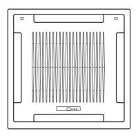
CASSETTE TYPE (50Hz)
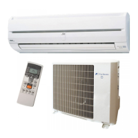
Indoor unit Outdoor unit
RC-25FA RO-25FA
RC-25UA RO-25UA
RC-25FA RO-25FB
RC-25UA RO-25UB
CONTENTS
SPECIFICATIONS . . . . . . . . . . . . . . . . . . .1
OUTLINE AND DIMENSIONS . . . . . . . . . . 2
CIRCUIT DIAGRAM . . . . . . . . . . . . . . . . .
4REFRIGERANT SYSTEM DIAGRAM . . . .
5
INDOOR PCB CIRCUIT DIAGRAM. . . . . .7
OUTDOOR PCB CIRCUIT DIAGRAM. . . .9
DISASSEMBLY ILLUSTRATION . . . . . . .11
PARTS LIST. . . . . . . . . . . . . . . . . . . . . . .19
ACCESSORIES . . . . . . . . . . . . . . . . . . . 22
ERROR CONTENTS . . . . . . . . . . . . . . . .10
Question and Answer IconNeed help?

Do you have a question about the Fuji Electric RC-25UA and is the answer not in the manual?

Fuji Electric RC-25UA Specifications

General IconGeneral
BrandFuji Electric
ModelRC-25UA
CategoryAir Conditioner
LanguageEnglish

Summary

SPECIFICATIONS

INDOOR UNIT OUTLINE AND DIMENSIONS

OUTDOOR UNIT OUTLINE AND DIMENSIONS

REFRIGERANT SYSTEM DIAGRAM

CIRCUIT DIAGRAM

INDOOR PCB CIRCUIT DIAGRAM

OUTDOOR PCB CIRCUIT DIAGRAM

ERROR CONTENTS

SELF-DIAGNOSIS

Procedure to perform self-diagnosis and interpret error codes displayed on the remote.

REMOTE CONTROLLER DISPLAY

Explanation of error codes as shown on the remote controller display.

OUTDOOR UNIT LEDS

Description of error indications using LED lamps on the outdoor unit.

DISASSEMBLY ILLUSTRATION

PARTS LIST - INDOOR UNIT

PARTS LIST - OUTDOOR UNIT

STANDARD ACCESSORIES

Related product manuals