EasyManua.ls Logo

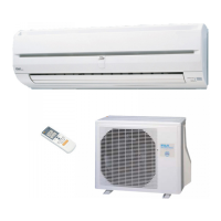
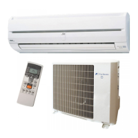
Fuji Electric RSG18LFCA User Manual

Fuji Electric RSG18LFCA
112 pages
To Next Page IconTo Next Page
Page #1 background imageLoading...
Page #1 background image
CONTENTS
SPECIFICATIONS . . . . . . . . . . . . . . . . . . .1
DIMENSIONS. . . . . . . . . . . . . . . . . . . . . . .8
REFRIGERANT SYSTEM DIAGRAM . . . 18
ERROR DETECTION. . . . . . . . . . . . . . . .60
CIRCUIT DIAGRAM . . . . . . . . . . . . . . . . .20
INDOOR PCB CIRCUIT DIAGRAM
. . . 30OUTDOOR PCB CIRCUIT DIAGRAM
. . . . .40
BRANCH BOX PCB CIRCUIT DIAGRAM
. . .36
PARTS (OUTDOOR UNIT) . . . . . . . . . . . 65
PARTS (BRANCH BOX) . . . . . . . . . . . . . 69
PARTS (INDOOR UNIT) . . . . . . . . . . . . . 72
ACCESSORIES . . . . . . . . . . . . . . . . . . .105
Indoor unit
RSG07LJCA
RSG09LJCA
RSG12LJCA
RSG18LFCA
RSG24LFCA
RCG07LVLA
RCG09LVLA
RCG12LVLA
RCG14LVLA
RCG18LVLA
CG-UFFD
RGG09LVCA
RGG12LVCA
RGG14LVCA
RDG07LLTA
RDG09LLTA
RDG12LLTA
RDG14LLTA
RDG18LLTA
RYG14LVTA
RYG18LVTA
Outdoor unit
ROG45LAT8
Branch box
UTP-PY02A
UTP-PY03A
Separation tube
UTP-SX248A
HYBRID FLEX INVERTER SYSTEM
Question and Answer IconNeed help?

Do you have a question about the Fuji Electric RSG18LFCA and is the answer not in the manual?

Fuji Electric RSG18LFCA Specifications

General IconGeneral
BrandFuji Electric
ModelRSG18LFCA
CategoryAir Conditioner
LanguageEnglish

Summary

Outdoor Unit Specifications

Fan Motor Specs

Fan motor details including discrimination and speed.

Compressor and Refrigerant

Details on the compressor and refrigerant used.

Branch Box Specifications

Electrical Data

Electrical specifications for the branch box.

Indoor Unit Compact Wall Mounted Specs (RSG07/09/12LJCA)

Indoor Unit Wall Mounted Specs (RSG18/24LFCA)

Indoor Unit Compact Cassette Specs (RCG)

Indoor Unit Floor Specs (RGG)

Indoor Unit Slim Duct Specs (RDG)

Indoor Unit Floor/Ceiling Specs (RYG)

Electrical Data and Fan Motor

Electrical data and fan motor specs for floor/ceiling indoor units.

Air Flow and Noise Level

Air flow rates and noise levels for floor/ceiling indoor units.

Outdoor Unit ROG45LAT8 Dimensions

Top, Front, and Side Views

Dimensional drawings of the outdoor unit from top, front, and side views.

Bottom and Rear Views

Dimensional drawings of the outdoor unit from bottom and rear views.

Branch Box UTP-PY02A Dimensions

Indoor, Ceiling, Outdoor Views

Dimensional views for branch box UTP-PY02A (indoor, ceiling, outdoor sides).

Wall Hanging View

Dimensional view for wall hanging configuration of UTP-PY02A branch box.

Indoor Unit Compact Wall Mounted Dimensions (RSG07/09/12LJCA)

Outline and Pipe Inlet Dimensions

Overall outline dimensions and pipe inlet details for the indoor unit.

Indoor Unit Wall Mounted Dimensions (RSG18/24LFCA)

Mounting Holes and Piping Details

Details on mounting holes and piping inlet locations for wall-mounted units.

Indoor Unit Compact Cassette Dimensions

Top, Side, and Bottom Views

Dimensional views of the compact cassette indoor unit from top, side, and bottom.

Indoor Unit Floor Dimensions (RGG09/12/14LVCA)

Front and Side Views

Dimensional drawings from front and side views for floor-type indoor units.

Indoor Unit Slim Duct Dimensions (RDG18LLTA)

Rear, Top, and Side Views

Dimensional drawings from rear, top, and side views for RDG18LLTA slim duct unit.

Refrigerant System Diagram

Piping Limitations and Specifications

Pipe Length Limitations

Maximum permissible lengths for refrigerant piping between system components.

Height Difference Limitations

Maximum allowable vertical height differences between system components.

Pipe Diameter and Refrigerant Charge

Refrigerant pipe diameters and additional charge requirements based on pipe size.

Outdoor Unit Circuit Diagram (ROG45LAT8)

Controller PCB (Main)

Circuit diagram connections for the main controller PCB in the outdoor unit.

Inverter and Filter PCBs

Circuit diagram connections for the inverter and filter PCBs in the outdoor unit.

Branch Box UTP-PY03A Circuit Diagram

Branch Box UTP-PY02A Circuit Diagram

Controller PCB Assembly Connections

Circuit diagram for controller PCB assembly connections in UTP-PY02A branch box.

Expansion Valve and Thermistor Connections

Circuit diagram for expansion valves and thermistors in UTP-PY02A branch box.

Indoor Unit Compact Wall Mounted Circuit Diagram (RSG07/09/12LJCA)

Fan Motor and Thermistor Connections

Circuit diagram showing fan motor and thermistor connections for indoor units.

Communication Kit UTY-XCBXZ1 Circuit Diagram

Indoor Unit Wall Mounted Circuit Diagram (RSG18/24LFCA)

Controller PCB and Fan Motor

Circuit diagram for controller PCB, fan motor, and louvers in wall-mounted indoor units.

Thermistor and Remote Control

Circuit diagram for thermistor and remote control connections in wall-mounted indoor units.

Indoor Unit Compact Cassette Circuit Diagram (RCG)

Controller and Power Supply PCBs

Circuit diagram for controller and power supply PCBs in compact cassette indoor units.

Indoor Unit Floor Circuit Diagram (RGG)

Indoor Unit Slim Duct Circuit Diagram (RDG)

Indoor Unit Floor/Ceiling Circuit Diagram (RYG)

Controller PCB and Thermistors

Circuit diagram for controller PCB and thermistors in floor/ceiling indoor units.

Outdoor Unit PCB Circuit Diagram (ROG45LAT8)

Power Source and Filter PCB

Circuit diagram for power source and filter PCB connections on the outdoor unit.

Controller and Inverter PCBs

Circuit diagram for controller and inverter PCB connections on the outdoor unit.

Outdoor Unit Controller PCB Primary Circuit Diagram

Outdoor Unit Controller PCB Secondary Circuit Diagram

Outdoor Unit Inverter PCB Circuit Diagram

Power Factor Correction (PFC) Circuit

Circuit diagram for the power factor correction (PFC) stage of the inverter.

Inverter Control and Driver Circuits

Circuit diagram for inverter control and driver circuits.

Outdoor Unit Filter PCB Circuit Diagram

EMI Filter and Surge Protection

Circuit diagram for EMI filter and surge protection components.

Outdoor Unit Indicator/I/O PCB Circuit Diagram

Branch Box Controller PCB Assembly 1 Circuit Diagram

Branch Box Controller PCB Assembly 2 Circuit Diagram

Indoor Unit PCB Circuit Diagram (RSG07/09/12LJCA)

Indoor Unit Controller PCB Circuit Diagram (RSG07/09/12LJCA)

Indoor Unit Indicator PCB Assembly Circuit Diagram

Communication PCB Assembly Circuit Diagram (UTY-XCBXZ1)

Indoor Unit Controller PCB Circuit Diagram (RSG18/24LFCA)

Power Supply and Voltage Regulation

Circuit diagram for power supply and voltage regulation circuits.

Microcontroller and Driver Circuits

Circuit diagram for microcontroller and driver circuits.

Indoor Unit Controller PCB Circuit Diagram (RSG18/24LFCA - Secondary)

Indoor Unit Power Supply PCB Circuit Diagram (RCG)

Indoor Unit Controller PCB Circuit Diagram (RCG)

Indoor Unit Controller PCB Circuit Diagram (RGG)

Fan Motors and Damper Connections

Circuit diagram for fan motors and damper connections in floor-type indoor units.

Indoor Unit Power Supply PCB Circuit Diagram (RYG)

Indoor Unit Indicator PCB Assembly Circuit Diagram (RYG)

Indoor Unit Controller PCB Circuit Diagram (RGG Floor)

Controller and Indicator PCBs

Circuit diagram for controller and indicator PCBs in floor-type indoor units.

Fan Motor and Damper Connections

Circuit diagram for fan motors and damper connections in floor-type indoor units.

Indoor Unit Controller PCB Circuit Diagram (RYG)

Fan Motor and Louver Connections

Circuit diagram for fan motors and louver connections in floor/ceiling indoor units.

Indoor Unit Indicator PCB Assembly Circuit Diagram (RGG)

Indoor Unit Power Supply PCB Circuit Diagram (RDG)

Indoor Unit Indicator PCB Assembly Circuit Diagram (RDG)

Outdoor Unit Error Detection

Error Code List

Table detailing error codes and their corresponding error contents for the outdoor unit.

Branch Box UTP-PY03A Error Detection

Branch Box UTP-PY02A Error Detection

Error Code Descriptions

Description of error codes and their corresponding meanings for UTP-PY02A branch box.

Indoor Unit Error Detection

Error Code and LED Indicator Mapping

Mapping of error codes to LED operation, timer, and economy indicators.

Error Code List (Indoor Unit Main PCB)

List of error codes and contents for the indoor unit main PCB.

Remote Control Error Displays

Simple Remote Controller Errors

Explanation of error display on the simple remote controller.

Wired Remote Controller Errors

Explanation of error display on the wired remote controller.

Central Remote Controller Errors

Explanation of error display on the central remote controller.

General Error Code List

Comprehensive list of error codes and their meanings across various system components.
Related product manuals