Do you have a question about the FujiFilm SonoSite SII and is the answer not in the manual?
Defines the intended readers of the manual, focusing on trained service personnel.
Provides crucial contact details for technical support and inquiries.
Explains the symbols, warnings, and formatting used throughout the service manual.
Describes the various symbols found on the ultrasound system and its packaging.
Provides general technical specifications for the ultrasound system and its compatibility.
Details the physical size, weight, and dimensions of the ultrasound system.
Specifies the size and dimensions of the system's display screen.
Outlines the operating, shipping, and storage conditions for temperature and humidity.
Details the system's power input requirements and output voltages.
Provides information on the battery's composition, runtime, and features.
Lists the various ultrasound imaging modes supported by the system.
Describes the system's capability for saving images and video clips.
Lists tested and recommended accessories and peripherals for the system.
Covers critical safety information regarding electrical hazards and precautions.
Details the system's classification regarding electrical safety standards.
Provides precautions necessary to protect the ultrasound system and its components.
Outlines essential safety guidelines for handling and charging the system's battery.
Addresses safety concerns related to patient care and medical procedures.
Provides information on handling and disposing of potentially hazardous materials.
Details the system's EMC compliance and precautions against interference.
Explains electrostatic discharge and precautions to prevent damage.
Provides recommended distances for RF equipment to prevent interference.
Includes declarations regarding electromagnetic emissions and immunity.
Summarizes the results of immunity testing performed on the system.
Lists the specific safety and EMC standards the system complies with.
References standards related to airborne equipment testing.
Information regarding the system's compliance with DICOM standards.
Information on the system's security features for HIPAA compliance.
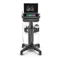
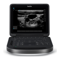
Provides a general description of the SonoSite SII ultrasound system's capabilities.
Explains the seven major functional groups and architecture of the ultrasound system.
Details the different imaging modes available, such as 2D and Color Doppler.
Highlights advanced features and performance capabilities of the system.
Describes the transmit and receive sections of the ultrasound system.
Explains the system's back-end processing for image rasterization and video output.
Details the components and architecture of the system's control subsystem.
Describes the system's power management, including battery and adapter functions.
Provides details on the rechargeable lithium-ion battery pack and its monitoring.
Explains the functionality of the external AC/DC adapter's battery charging circuitry.
Describes the system's Digital Imaging and Communications in Medicine capabilities.
Procedure to format the system SD memory and erase patient data.
Procedure to revert system settings back to factory defaults.
Basic diagnostic procedures for identifying system operational failures.
Information on system repair through subassembly replacement.
Lists the required test equipment for troubleshooting tasks.
Explanation of system error codes related to hardware and software issues.
Steps to diagnose the cause of system assert codes for recovery.
Troubleshooting common issues related to DICOM network communication.
Solutions for problems encountered with the system's user interface.
Guidance for diagnosing and resolving issues related to the system battery.
Lists the necessary tools for performing component replacements.
Detailed steps for removing the user interface assembly from the system.
Instructions for transferring specific parts from the old to the new UI.
Steps for installing individual parts onto the new User Interface assembly.
Procedure for installing the new User Interface assembly onto the base.
Procedures for disassembling the system's base assembly for repair.
Procedure for replacing the Power Button Printed Circuit Board Assembly.
Procedure for replacing the system's back enclosure.
Procedure for replacing the internal mini-dock assembly.
Procedure for replacing the Dual/Single Transducer Connectors.
Procedure for replacing the dual fan cable assembly.
Procedure to remove the power supply Printed Circuit Board Assembly.
Information regarding the field-replaceability of the SD card.
Procedure for replacing the main Printed Circuit Board Assembly.
Procedure for replacing the system's mid-frame assembly.
Details on routine maintenance, primarily transducer cleaning and disinfection.
Introduction to the performance testing procedures for the ultrasound system.
Lists the essential equipment required for performing system performance tests.
Guidance on preparing the system and phantom for performance testing.
Tests to verify fundamental system functions and basic operation.
Procedures for evaluating the 2D imaging performance and quality.
Tests to measure and verify the accuracy of axial distance measurements.
Tests to measure and verify the accuracy of lateral distance measurements.
Procedure to test the system's ability to provide adequate image quality at depth.
Covers other specific performance tests for various imaging modalities.
Procedure for testing the performance of the Color Doppler imaging mode.
Procedure for testing the performance of the Color Power Doppler imaging mode.
Procedure for testing the performance of the M Mode imaging.
Procedure for testing the performance of Tissue Harmonic Imaging.
Final validation of image quality after service procedures.
Test for the optional video printer's functionality.
Procedure to verify the battery charging system's operation.
Test for the optional external video monitor connection.
Lists the part numbers for components within the system's base assembly.
Lists supplementary part numbers for the base assembly.
Lists the part numbers for various user interface components.
Identifies parts specifically required for STC system configurations.
Lists the part numbers for the external casing and enclosure components.
Lists the part numbers for the transducer nest frame assembly.
Provides instructions and contact information for ordering replacement parts.
The standardized form used for documenting product failures and service.
Guidance on how to properly complete the service event report form.
Procedures and information required when returning products for service.
Guidelines for shipping products back to FUJIFILM SonoSite.
| Brand | FujiFilm |
|---|---|
| Model | SonoSite SII |
| Category | Medical Equipment |
| Language | English |