Do you have a question about the Fujitsu ABYA54LCT and is the answer not in the manual?
Details electrical characteristics of the unit models, including capacity, power source, and current ratings.
Information on compressor type, refrigerant type, pre-charged refrigerant, and pipe length/charge limits.
Specifications for indoor and outdoor fan motor speeds (RPM) across different operating modes.
Sound pressure levels (dB) for indoor and outdoor units at various fan speeds.
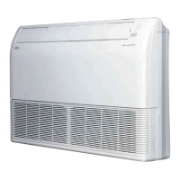
Physical dimensions (Height x Width x Depth) for indoor and outdoor units.
Gross and net weight specifications for both indoor and outdoor units.
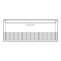
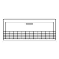
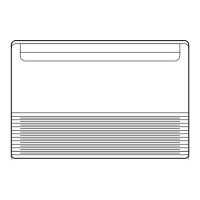
Detailed diagrams and measurements (mm) for the indoor unit's physical layout.
Detailed diagrams and measurements (mm) for the outdoor unit's physical layout.
A visual diagram illustrating the refrigerant flow and key components within the system.
Electrical schematic detailing the wiring and connections for the indoor unit.
Electrical schematic detailing the wiring and connections for the outdoor unit.
Detailed circuit diagram of the indoor unit's Printed Circuit Board (PCB) and its connections.
Detailed circuit diagram of the outdoor unit's Printed Circuit Board (PCB) and its connections.
Table mapping indicator lamp flashing patterns to specific indoor unit error codes and contents.
List of error codes and their corresponding meanings displayed on the remote control's LCD.
Procedures for verifying conditions and executing the test run operation for the outdoor unit.
Table correlating LED blinking counts to specific outdoor unit error types for troubleshooting.
Guide to collecting refrigerant prior to unit disconnection, including preparation and operational steps.
Exploded view and comprehensive list of indoor unit components with their respective part numbers.
Exploded view and comprehensive list of outdoor unit components with their respective part numbers.
List of optional accessories and consumables provided for both indoor and outdoor units.
| Model | ABYA54LCT |
|---|---|
| Cooling Capacity | 5.4 kW |
| Heating Capacity | 6.0 kW |
| Power Supply | 220-240 V, 50 Hz |
| Outdoor Unit Noise Level | 50 dB |