Outdoor unit1
(Master unit)
IN/U
IN/U
RB unit
RB unit
Refrigerant piping
Dedicated cooling device
Transmission
Outdoor unit 2
(Slave unit 1)
Outdoor unit 3
(Slave unit 1)
Transmission
Transmission Transmission
Transmission
IN/U
Transmission
Terminal -
Resistance
53 Ohm
< Main PCB >
-SET 5-4:ON-
Terminal Resistance
53 Ohm
<Main PCB>
-Internal circuit -
Terminal Resistance
53 Ohm
<Main PCB>
-Internal circuit -
Terminal Resistance
53 Ohm
<Main PCB>
-Internal circuit -
TransmissionTransmission
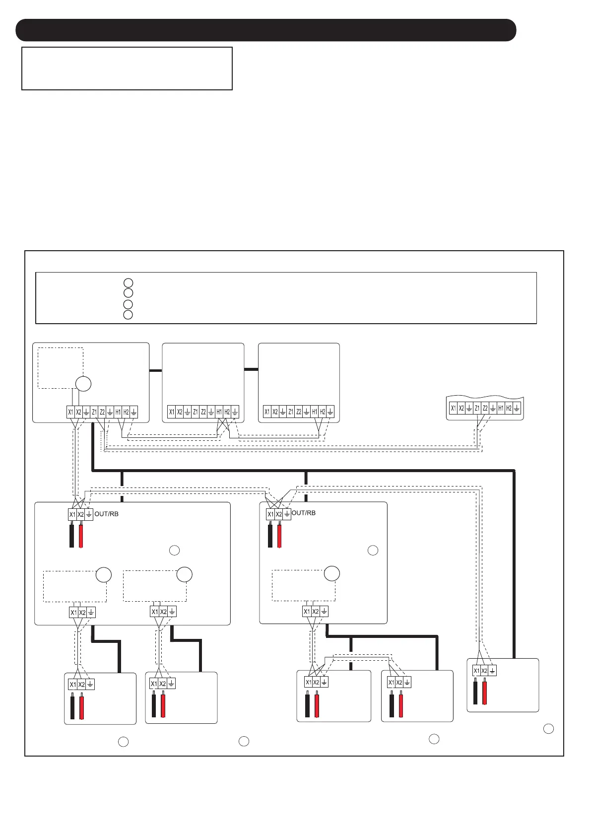
- Basic trouble shooting procedure -
1. Check Error code in one network segment separately, and check the Error code of (OU, IU, RB Error LED, RC, ST)
< If the system has more than 2 Net work segments, disconnect the other Network segment.>
2. Connect Service tool to the Outdoor unit, and try out "Address checker" Function by the Service toll.
< Check missing indoor unit or RB unit or outdoor unit by using Address checker function of Service tool>
3. Check terminal resistance value 53 Ohm + 5% + Line Resistance on the terminal borad one by one.
< Terminal Resistance is located on the Outdoor unit PCB(activated SET 5-4 ON), and the Main PCB of RB Unit each >
*Refer to the wiring diagram of Networlk cable
To other refrigerant circuit
Outdoor unit
A
B
C
D
Measurement
Terminal Resistance A
Measurement
Terminal Resistance A
Measurement
Terminal Resistance A
Measurement
Terminal Resistance B
Measurement
Terminal Resistance C
Measurement
Terminal Resistance D
4-3 SERVICE INFORMATION
SERVICE INFORMATION
Network communication Abnormal
Indoor Unit
Cooling Only
Indoor unit 4
Indoor unit 3
Indoor unit 2
Indoor unit 1
Terminal Resistance A is located on the controller PCB of Outdoor unit as the Network for RB unit, Cooling only Indoor unit
Terminal Resistance B is located on the Main PCB of RB unit as the Network for Indoor unit 1
Terminal Resistance C is located on the Main PCB of RB unit as the Network for Indoor unit 2
Terminal Resistance D is located on the Main PCB of RB unit as the Network for Indoor unit 3 and Indoor unit 4
-
Exsample
04-89
 Loading...