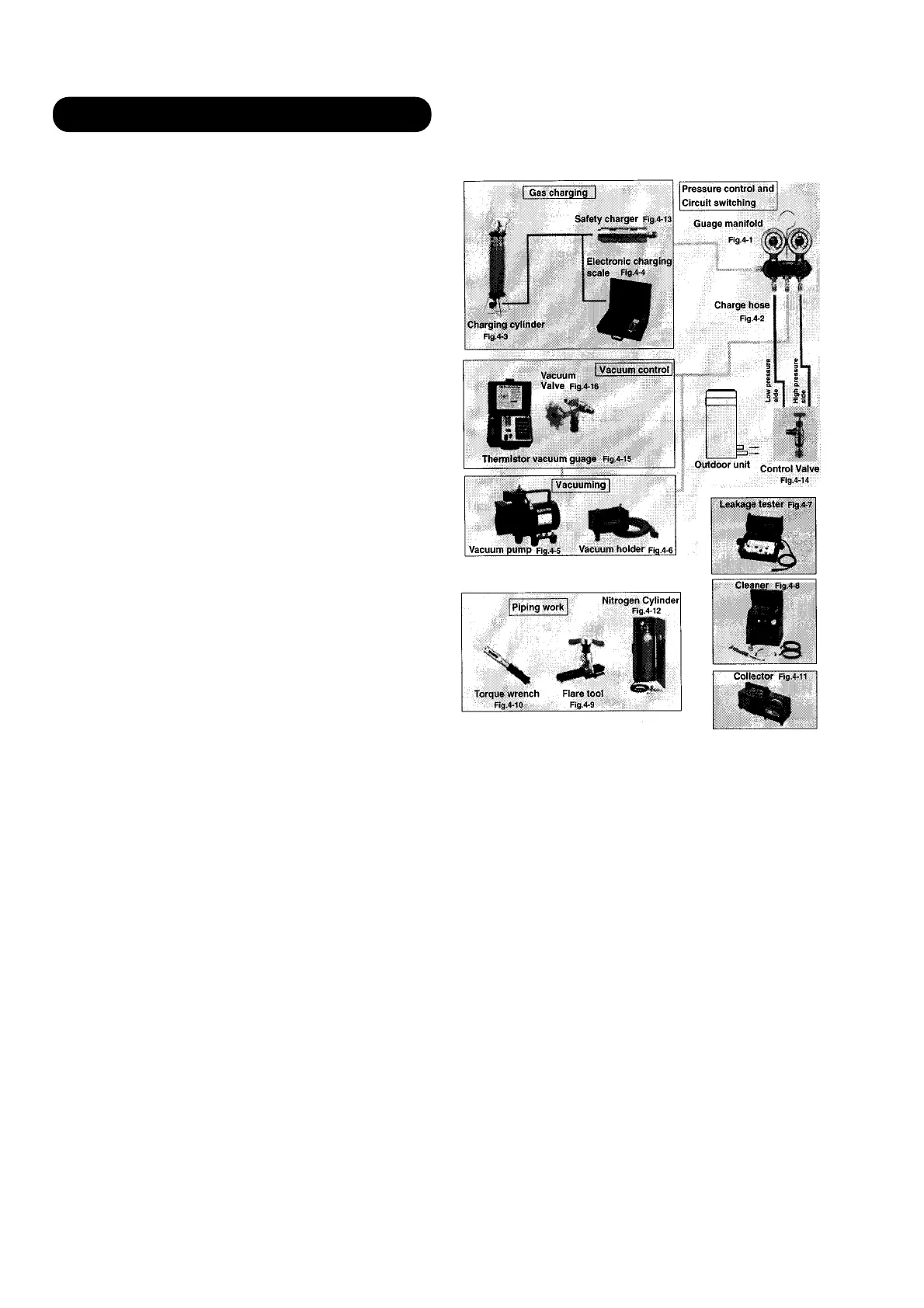
9-4 Tools
Gauge manifold . . . . . . . . . . . . . . . . . . . . . (Fig.4-1)
Pressure gauge changed.
Charge hose . . . . . . . . . . . . . . . . . . . . . . . (Fig.4-2)
Changed to HFC resistant material.
Charging cylinder . . . . . . . . . . . . . . . . . . . (Fig.4-3)
Gauge changed
Electronic balance for refrigerant
charging . . . . . . . . . . . . . . . . . . . . . . . . . . . (Fig.4-4)
Electronic balance is recommended as in the case of
R410A.
Vacuum pump with adapter to prevent
reverse flow . . . . . . . . . . . . . . . . . . . . . . . .(Fig.4-5)
Conventional pump can be used.
Vacuum holder . . . . . . . . . . . . . . . . . . . . . (Fig.4-6)
Conventional pump can be used if adapter for preventing
vacuum pump oil from flowing back is used.
Gas leakage tester . . . . . . . . . . . . . . . . . . (Fig.4-7)
Exclusive for HFC
Refrigerant cleaner . . . . . . . . . . . . . . . . . . (Fig.4-8)
Brown paint as designated by the ARI, USA
Flare tool . . . . . . . . . . . . . . . . . . . . . . . . . . (Fig.4-9)
Conventional tool can be used.
Torque wrench . . . . . . . . . . . . . . . . . . . . (Fig.4-10)
Conventional wrench can be used.
Refrigerant recovering
equipment (Collector) . . . . . . . . . . . . . . (Fig.4-11)
The type which can be used for any refrigerant is available
Nitrogen cylinder . . . . . . . . . . . . . . . . . . . (Fig.4-12)
This prevents an oxide film from forming in the pipe silver-
alloy brazing work by turning the air out of the pipe and
preventing the inside combustion.
Safety charger . . . . . . . . . . . . . . . . . . . . . (Fig.4-13)
It is always compulsory to change the liquid, because
R407C is a mixed refrigerant and there is some fear that a
mixing ratio changes. In order to avoid the refrigerant from
returning to the compressor in a liquid state, the refrigerant
can be charged instead of giving a load to the compressor
with a safety charger.
Control valve . . . . . . . . . . . . . . . . . . . . . . (Fig.4-14)
The control valve prevents the refrigerant from spouting
when it is removed, as the charging hose side and the ser-
vice port side are possible to open and close at the same
time.
Thermistor vacuum gauge . . . . . . . . . . . (Fig.4-15)
To remove moisture from the refrigerating cycle complete-
ly, it is necessary to perform appropriate vacuum drying.
For that reason, vacuum conditions can be confirmed cer-
tainly.
Vacuum valve . . . . . . . . . . . . . . . . . . . . . (Fig.4-16)
This valve builts in a check valve, and it is easily possible
to vacuum a refrigerating cycle or check for degree of vac-
uum with it.
TOOLS AND EQUIPMENT (R407C)
– 132 –
 Loading...