Do you have a question about the Fujitsu ARYA45LCTU and is the answer not in the manual?
Detailed electrical characteristics of the unit.
Sound pressure levels for indoor and outdoor units.
Information on the compressor type and refrigerant details.
Specifications for indoor and outdoor fan motors.
Physical dimensions of the indoor and outdoor units.
Shipping and net weights for indoor and outdoor units.
Detailed drawings with dimensions for the indoor unit.
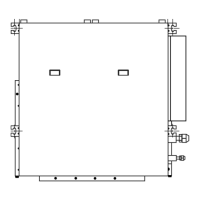
Detailed drawings with dimensions for the outdoor unit.
Diagram illustrating refrigerant flow in outdoor and indoor units.
Wiring diagram for the indoor unit and associated PCBs.
Wiring diagram for the outdoor unit and associated PCBs.
Schematic for the main controller PCB.
Schematic for the indicator PCB.
Schematic for the transistor PCB (IPM).
Schematic for the capacitor PCB.
Wiring details for the indoor unit control system.
Wiring diagram for the power supply PCB assembly.
Wiring diagram for the main controller PCB assembly.
Wiring connections for the remote control unit.
Detailed schematic diagram of the indoor unit's main controller PCB.
Wiring connections for the outdoor unit inverter assembly.
Wiring diagram for the outdoor unit power supply PCB.
Wiring diagram for the outdoor unit capacitor PCB.
Wiring diagram for the outdoor unit transistor PCB.
Wiring diagram for the outdoor unit main controller PCB.
Wiring diagram for the outdoor unit indicator PCB.
Detailed schematic of the outdoor unit controller PCB.
Continuation of the outdoor unit controller PCB schematic.
Detailed schematic of the outdoor unit transistor PCB (IPM).
Wiring and switch connections for the outdoor unit indicator PCB.
Schematic diagram for the outdoor unit capacitor PCB.
Guide to identifying errors using the wired remote control display.
Identifying errors through lamp flashing on the receiver unit.
Error codes indicated by LED blinks on the outdoor unit indicator PCB.
Step-by-step guide for performing the outdoor unit test run.
Detailed steps for performing the refrigerant pump down operation.
Illustrated list of parts for the indoor unit.
Further illustrated list of parts for the indoor unit.
Illustrated parts list for the indoor unit's control unit.
Illustrated list of exterior parts for the outdoor unit.
Illustrated parts list for the outdoor unit's control box.
Illustrated list of internal components for the outdoor unit.
List of accessories available for the indoor unit.
Optional exterior parts with specifications and models.
Optional parts for the outdoor unit.
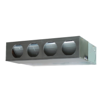
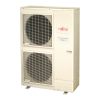
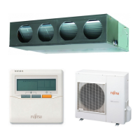
This document provides a comprehensive service manual for the FUJITSU SPLIT TYPE AIR CONDITIONER, specifically for DUCT TYPE (50Hz) models ARYA45LCTU (Indoor Unit) and AOYA45LCTL (Outdoor Unit), which utilize R410A refrigerant.
The manual outlines the function description of the air conditioning system as a split-type unit designed for duct installation, providing both cooling and heating functionalities. It details the electrical, performance, and physical characteristics of both the indoor and outdoor units, along with circuit diagrams, error detection procedures, and parts lists.
Important technical specifications are meticulously detailed in the "SPECIFICATIONS" section. For ELECTRICAL DATA:
For NOISE LEVEL:
For COMPRESSOR AND REFRIGERANT:
For FAN MOTOR:
For DIMENSIONS:
For WEIGHT:
The manual also includes detailed refrigerant system diagrams and circuit diagrams for both indoor and outdoor units, including PCB circuit diagrams (Main PCB, Indicator PCB, Transistor PCB, Capacitor PCB, Power Supply PCB, Filter PCB) which are crucial for understanding the internal workings and for troubleshooting.
Usage features are primarily addressed through the "TEST RUN" and "PUMP DOWN" procedures. The "TEST RUN" section guides the user through a systematic check of the outdoor unit's installation and operation, including:
The "PUMP DOWN" procedure is critical for maintenance features related to refrigerant handling. It outlines the steps to safely collect refrigerant before disconnecting any pipes or electrical cables. Key warnings are provided regarding electrical shock and abnormal pressure if procedures are not followed correctly. The process involves:
Maintenance features are further supported by extensive error detection capabilities. The system provides self-diagnosis through both wired remote control and the receiver unit display. For wired remote control:
The manual concludes with detailed parts lists for both indoor and outdoor units, including descriptions and part numbers for major components (e.g., intake cover, main panel, drain pan, evaporator, fan motor, controller PCB, power supply PCB, compressor, valves, sensors, chokes, capacitors, transistors). Accessories such as hangers, special nuts, coupler heat insulation, binders, drain hose insulation, remote controls, and tapping screws are also listed with their applications and part numbers. Optional parts like square/round flanges, long-life filters, remote sensors, external control sets, and drain pump units are also detailed.
| Brand | Fujitsu |
|---|---|
| Model | ARYA45LCTU |
| Category | Air Conditioner |
| Language | English |