S
Susan CraigNov 4, 2025
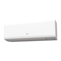
What to do if Fujitsu ASHG07KGTE Air Conditioner indoor unit has no power?
- SslewisNov 4, 2025
If your Fujitsu Air Conditioner indoor unit has no power, start by checking the installation condition, as it may be due to a power supply failure. Also, check for any external causes at the indoor and outdoor units, such as voltage drops or noise. Ensure there isn't a large electrical appliance on the same circuit. Inspect the power supply circuit for defective contacts or leak current. Verify there's no equipment causing harmonic waves near the electrical line, and confirm the grounding insulation is complete. Check the power supply voltage and ensure AC 198 to 264 V appears at the outdoor unit terminal 1—2. Examine the fuse and varistor in the filter PCB. If the fuse is open, check for loose wiring and replace it. If the varistor is defective, check for an abnormal power supply and repl...