SERVICE PARTS INFORMATION 9
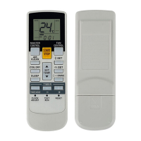
IPM
(Mounted on Transistor PCB)
02-58
Test 1 : Check the Transistor of PCB ( for Resistance )
Test 2 : Check the Transistor of PCB ( for Diode )
Terminal
Resistance value
Tester(+) Tester(-)
Disconnect the connection wires between the Transistor
PCB - Capacitor PCB and Transistor PCB - Inverter
Compressor.
Set the tester to the "Resistance" mode, and measure
the resistance between the following terminals.
Set the tester to the "Diode" mode, and measure the voltage value between the following terminals.
Judge the result of as follows:
Judge the result of as follows:
IC400-30 (P) - TM403(U) / TM404(V) / TM405(W)
IC400-24 (N) - TM403(U) / TM404(V) / TM405(W)
P
P
P
U
V
W
N
N
N
U
V
W
U
V
W
P
P
P
U
V
W
N
N
N
Over 2k
(Including )
Over 2k
(Including )
Over 20k
(Including )
Terminal
Tester display
Tester(+) Tester(-)
P
P
P
U
V
W
N
N
N
U
V
W
U
V
W
P
P
P
U
V
W
N
N
N
0.3V 0.7V
 Loading...