En-12
(♦... Factory setting)
Function Number
Setting
Value
Setting Description
95
00 Standard insulation ♦
01 High insulation
■
Room temperature control for indoor unit sensor
Depending on the installed environment, correction of the room temperature sensor may
be required.
Select the appropriate control setting according to the installed environment.
The temperature of the room temperature sensor is corrected as follows:
Corrected temp. = Temp. of room temp. sensor - correction temp. value
Example of correction :
When the temperature of room temp. sensor is 78 °F and the setting value is
“03” (-2 °F), the corrected temp. will be 80 °F (78 °F [-2 °F]).
The temperature correction values show the difference from the “Standard setting” (00)
(manufacturer’s recommended value).
(♦... Factory setting)
Function number
Setting
value
Setting description
30
(For cooling)
31
(For heating)
00 Standard setting ♦
01 No correction 0 °F (0.0 °C)
02 -1 °F ( -0.5 °C)
More
Cooling
Less
Heating
03 -2 °F (-1.0 °C)
04 -3 °F (-1.5 °C)
05 -4 °F (-2.0 °C)
06 -5 °F (-2.5 °C)
07 -6 °F (-3.0 °C)
08 -7 °F (-3.5 °C)
09 -8 °F (-4.0 °C)
10 +1 °F (+0.5 °C)
Less
Cooling
More
Heating
11 +2 °F (+1.0 °C)
12 +3 °F (+1.5 °C)
13 +4 °F (+2.0 °C)
14 +5 °F (+2.5 °C)
15 +6 °F (+3.0 °C)
16 +7 °F (+3.5 °C)
17 +8 °F (+4.0 °C)
■
Room temperature control for wired remote controller sensor
Depending on the installed environment, correction of the wire remote temperature sensor
may be required.
Select the appropriate control setting according to the installed environment.
To change this setting, set Function 42 to “Both” (01).
Ensure that the Thermo Sensor icon is displayed on the remote controller screen.
(♦... Factory setting)
Function number
Setting
value
Setting description
35
(For cooling)
36
(For heating)
00 No correction ♦
01 No correction 0 °F (0.0 °C)
02 -1 °F ( -0.5 °C)
More
Cooling
Less
Heating
03 -2 °F (-1.0 °C)
04 -3 °F (-1.5 °C)
05 -4 °F (-2.0 °C)
06 -5 °F (-2.5 °C)
07 -6 °F (-3.0 °C)
08 -7 °F (-3.5 °C)
09 -8 °F (-4.0 °C)
10 +1 °F (+0.5 °C)
Less
Cooling
More
Heating
11 +2 °F (+1.0 °C)
12 +3 °F (+1.5 °C)
13 +4 °F (+2.0 °C)
14 +5 °F (+2.5 °C)
15 +6 °F (+3.0 °C)
16 +7 °F (+3.5 °C)
17 +8 °F (+4.0 °C)
■
Setting record
•
Record any changes to the settings in the following table.
Function
number
Setting Description
Setting Value
95 Heat Insulation condition (building insulation)
30
Room temperature control for indoor unit
sensor
Cooling
31 Heating
35
Room temperature control for wired remote
controller sensor
Cooling
36 Heating
After completing the Function setting, be sure to disconnect the power and reconnect it
again.
6. TEST RUN
■
Check items
(1) Is operation of each button on the remote control unit normal?
(2) Does each lamp light normally?
(3) Do air ow direction louvers operate normally?
(4) Is the drain normal?
(5) Do not have an abnormal noise and vibration during operation?
(6) Is there an error left in the error memory?
• After installation, check that the display is “00 (normal)”.
(For checking whether the display shows “00”, refer to “
■Service check in the Operation
manual”.)
- If the display is other than “00 (normal)” even though it works normally, erase the error
memory
- For “
■How to check the error memory” and “■How to erase the error memory”, refer
to the lower section of the “9. ERROR CODES” list.
• Do not operate the air conditioner in test run for a long time.
(If you leave it as it is after the test run starts, it will end automatically in about 60
minutes.)
■
Operation method
Before starting the test run, wait for 1 minute after connecting the power supply.
By the wireless remote controller
• To start the test run, press [START/STOP(
)], press and hold [ ] on the remote
control for 5 seconds or more by using the tip of a ballpoint pen or other small object.
By the indoor unit
• To start the test run, keep on pressing the indoor unit button for more than 10 seconds.
• To end test operation, press the remote controller [START/STOP(
)].
(When the air conditioner is running by pressing [
], the “OPERATION” Lamp and
“TIMER” Lamp will simultaneously ash slowly.)
7. FINISHING
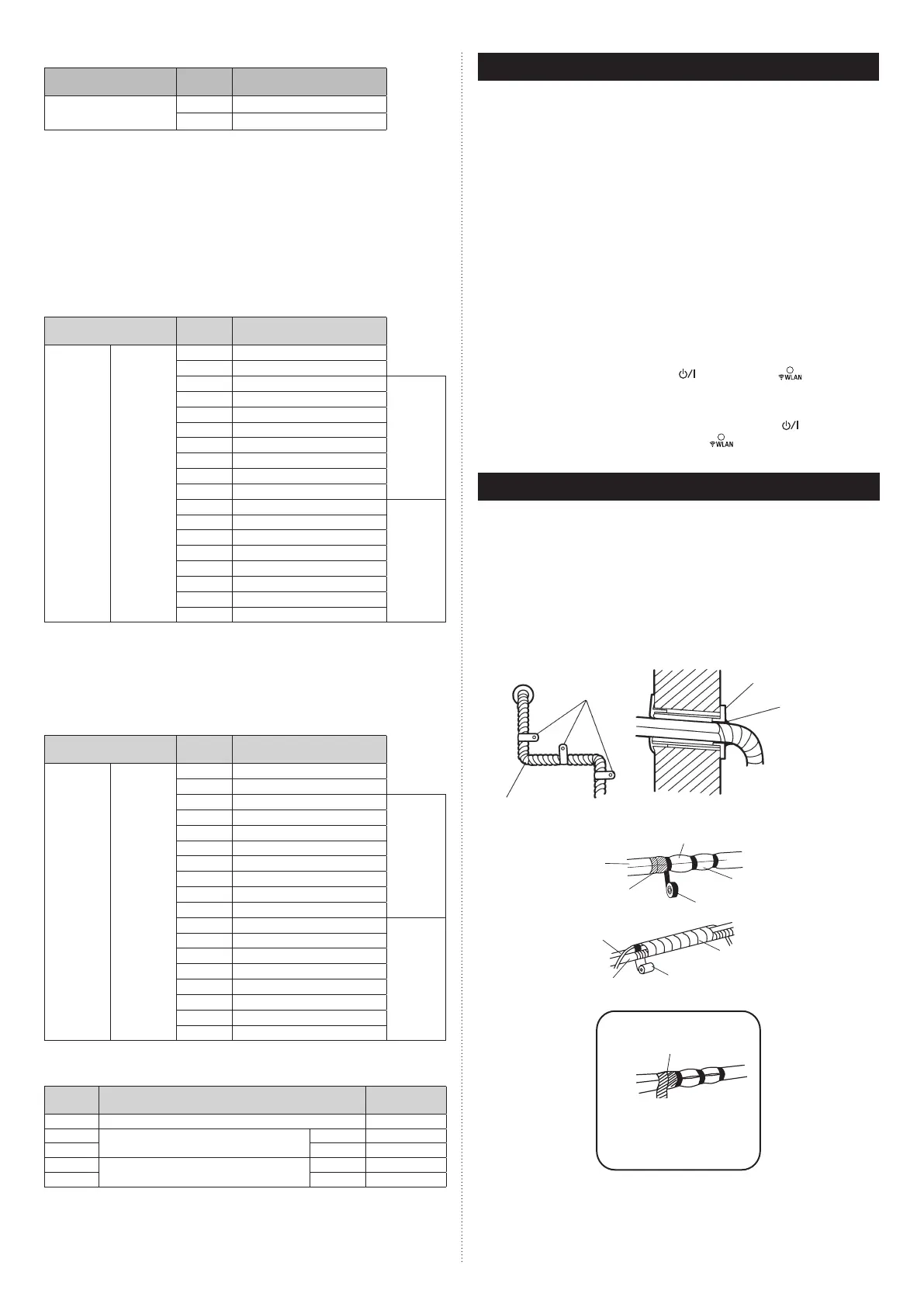
(1) Insulate between pipes.
• Insulate suction and discharge pipes separately.
• For rear, right, and bottom piping, overlap the connection pipe heat insulation and
indoor unit pipe heat insulation and bind them with vinyl tape so that there is no gap.
(2) Temporarily fasten the connection cable along the connection pipe with vinyl tape.
(Wrap to about 1/3 the width of the tape from the bottom of the pipe so that water
does not enter.)
(3) Fasten the connection pipe to the outside wall with a saddle, etc.
(4) Fill the gap between the outside wall pipe hole and the pipe with sealer so that rain
water and wind cannot blow in.
(5) Fasten the drain hose to the outside wall, etc.
(6) Check the drainage.
*Locally purchased
Pipe
Saddle*
Outside wall cap*
Sealer putty*
(Outdoors)
Wall
Overlap the insulation
Vinyl tape*
Wrap with cloth tape.
Cloth tape (accessory)
Drain hose
Pipe
Connection pipe
(heat insulation)
Indoor unit pipe
(heat insulation)
Bind the pipes together
so that there is no gap.
Drain hose insulation is used
when the diameter of gas pipe is
Ø12.70 or more.
Butt connection pipe (heat
insulation) against the indoor unit
pipe (heat insulation) and wrap
with drain hose insulation so that
there is no gap.
9387082593-01_IM.indb 129387082593-01_IM.indb 12 28-Oct-21 13:52:5728-Oct-21 13:52:57
 Loading...