En-7
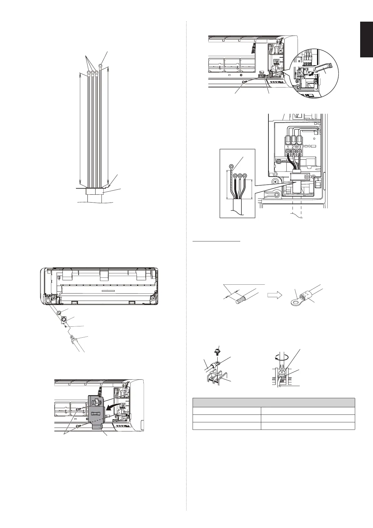
(2) Remove the tapping screw and while minding the cable clamp hook, remove the cable
clamp.
Screw
Cable clamp
Cable
clamp
Hook
(3) Use the wire with ring terminals to connect to the terminal block.
1 in (25 mm)
2.5 in (65 mm)
Ground (Earth)
wire
3.4.4. How to connect wiring to the terminals
■
Caution when wiring cable
Caution when wiring cable
When stripping off the insulation of a lead wire, always use a special tool such as a wire
stripper. If there is no special tool available, carefully strip the insulation with a knife etc.
(1) Use ring terminals with insulating sleeves as shown in the following gure to connect
to the terminal block.
(2) Securely clamp the ring terminals to the wires using an appropriate tool so that the
wires do not come loose.
Strip: 3/8 in (10 mm)
Ring terminal
Sleeve
(3) Use the specied wires, connect them securely, and fasten them so that there is no
stress placed on the terminals.
(4) Use an appropriate screwdriver to tighten the terminal screws. Do not use a screw-
driver that is too small, otherwise, the screw heads may be damaged and prevent the
screws from being properly tightened.
(5) Do not tighten the terminal screws too much, otherwise, the screws may break.
Screw with special washer
Wire
Ring terminal
Terminal blocks
Wire
Screw with special washer
Ring terminal
(6) Refer to the following table for the terminal screw tightening torques.
Tightening torque [lbf·in (N·m)]
M3.5 screw 7.0 to 8.8 (0.8 to 1.0)
M4 screw 10.6 to 15.9 (1.2 to 1.8)
M5 screw 17.7 to 26.5 (2.0 to 3.0)
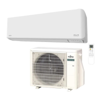
• To connect the indoor unit wires to the terminal correctly, refer to the gure for proper
length.
Unit: in (mm)
14AWG
Ground (earth) wire
Conduit holder
Conduit connector
9-1/16(230)
9-7/16(240)
3.4.2. How to the install the connection cable
(1) Remove the screws, then remove the conduit holder.
(2) Fasten the indoor unit wire harness to the conduit holder using the lock nut.
IMPORTANT: Refer to “3.4.1. Wiring system diagram” about the length of indoor unit
wire harness.
(3) Use the screws to install the conduit holder provide with the indoor unit.
(4) Remove the screws, then remove the cable clamper.
(5) Connect indoor unit wire harness to the terminal.
Refer to “3.4.1. Wiring system diagram”.
(6) Use the screws to install the cable clamper.
Lock nut
Conduit holder
Conduit connector
Screw
3.4.3. Indoor unit wiring
(1) Open the intake grille. Remove the tapping screw for the wire cover and remove the
wire cover.
Screw
Wire cover
9387082593-01_IM.indb 79387082593-01_IM.indb 7 28-Oct-21 13:52:5128-Oct-21 13:52:51
 Loading...