Do you have a question about the Fujitsu MB91460 SERIES and is the answer not in the manual?
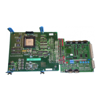
Brief summary of the evaluation board's purpose and capabilities.
Lists the key hardware and software features of the evaluation board.
Detailed explanation of the board's components and functionality.
Instructions for connecting power and initial setup of the evaluation board.
Lists default jumper configurations for the starter kit.
Visual guide showing the physical locations of jumpers on the board.
Steps to install the necessary development software (Softune Workbench).
Configuration of DIP switch S1 for single chip and serial programming modes.
Configuration of DIP switch S1 for serial programming mode.
Details on power switch and jumper settings for board power configuration.
Configuration of analog power supply and reference voltage for A/D converter.
Configuration of serial interfaces for LIN and UART communication.
Configuration of CAN interfaces for network communication.
Settings for external and UART-based reset generation.
Configuration of user push buttons for input functions.
Configuration options for Flash, SRAM, and SDRAM access modes.
Details of the DC power input and pin assignments for edge connectors.
Pinout and signal descriptions for serial and CAN communication connectors.
Information on the onboard LEDs and their control.
Details on external bus interface connectors (VG96ABC and VG48ABC).
Procedure for programming internal flash using asynchronous serial mode.
Information on programming internal flash using synchronous mode.
Configuration settings for programming the SWB Monitor Debugger.
List of related Fujitsu products and accessories.
Links to Fujitsu websites for product information and support.
Glossary of technical abbreviations used in the document.
| Architecture | 32-bit |
|---|---|
| ADC | 16 channels |
| Timers | Multiple 16-bit timers/counters |
| Communication Interfaces | CAN, UART, SPI, I2C |
| Package | LQFP, QFP |