ACコード
モニタ
ケーブル
USB
ケーブル
PS/2
ケーブル
(MS)
PS/2
ケーブル
(KB)
キーボード・マウスポート
(USB、PS/2どちらか一方を接続)
モニタポート
電源コンセント
Virtual Media Port (U
Installing the RC25 Rack Mount Kits to the Rack Connecting Cables
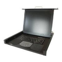
Inserting the Rack Console
(1) Pull out the intermediate members of the slide rails until the members are locked.
(2) Pull out the retainers to the front ends of the rails.
(3) Insert the Rack Console into the slide rails. Push the Rack Console until it locks on the slide
rails.
Storing the Rack Console
(1) Push the fixing springs on the ends of the right and left slide rails, and slide the device back
into the rack slowly.
(2) Tighten the finger screws on the right and left front ends of the device.
Installing the Cable Management Part
Select either the PS/2 cable or USB cable as the cable to
connect the keyboard and mouse. If both cables are connected
and any operational problem occurs on the keyboard or mouse,
the server must be rebooted.
Finger
screws
NC14010-L593-02
Opening and Closing the Monitor
To open the monito
(1) Grip the monitor handle and open the monitor upward.
To close the monitor
(1) Make sure that nothing is connected to the Virtual Media USB port on the front side of the
device.
(2) Hold the handle and slowly close the monitor downward.
Handle
Virtual Media Por
(USB)
Rear bracket
Be careful not to pinch your hands or fingers in the slide rails or
Rack Console itself when you stow the Rack Console.
When you open the monitor upward, if you cannot open it with one
hand or you feel it is too heavy to open with one hand, open it with
both hands.
When closing the monitor, make sure there is nothing connected to
the front Virtual Media USB port, and be careful to not pinch your
fingers between the monitor and the keyboard.
Finger screw
(2) Fix the front bracket to the fitting on the rear of
the Rack Console.
(3) Insert the pin for fixing the cable management
part into the hole.
Firmly push the pin until the ball lock is securely
in place.
Bracket
Pin for fixing
the cable
management
part
Ring for removing
the pin
If the ring for removing the pin
rests on the Rack Console or
RC25 Rack Mount Kit after the pin has
been inserted, it might not be possible to
store the Rack Console. Therefore, be
sure that the ring rests on the center of the
unit as shown in this figure.
(1) Secure the rear bracket of the cable management part with the finger screw on the rear
protrusions of the RC25 Rack Mount Kit on the left rear-side rack brace.
Connect the following cables to this device as
shown in this figure, so there is no slack.
AC power cable on bottom
Monitor cable on top
If the cables are pulled too tightly after
connecting the monitor cable to this device,
adjust the lengths of the cables.
To remove the RC25 Rack Mount Kit:
(1) Insert the unlocking tool between the Easy
mounting-clip and the Security lock as shown in
the figure, and then remove the Security lock.
(2) Insert the unlocking tool into the opening in
the Easy mounting-clip, disengage the lock, and
then remove the RC25 Rack Mount Kit from
the front-side rack brace.
Rear-side
rack braces
RIGHT
LEFT
Cage nut
Security
locks
Protrusions
(1) Attach one cage nut on each of the right and left front-side rack braces, and attach another
cage nut on the left rear-side rack brace.
(2) Insert the two protrusions on the rear side of the RC25 Rack Mount Kits into the rear-side
rack braces, so that the inserted RC25 Rack Mount Kits are at the same height unit (U).
One RC25 Rack Mount Kit is for the left rear-side rack brace and the other is for the right. Find the
letters LEFT or RIGHT on the side of each RC25 Rack Mount Kit and attach each RC25 Rack
Mount Kit to the suitable side of the rack.
(3) Keep the RC25 Rack Mount Kits horizontal at the same height unit (U) and attach them to
the front-side rack braces.
Check that the Easy mounting-clips and centering screws are inserted firmly into the front-side
rack braces.
(4) Insert the Security locks into the left and right Easy mounting-clips on the front side of the
RC25 Rack Mount Kits.
Cage nut
Left rear-side rack brace
(asymmetrical PRIMERGY rack)
Centering screws M5 Torx T20
Su
ort bracket
Front-side rack brace
Cage nut
Cage nut
To install in an asymmetrical PRIMERG
rack:
(1) Use two centering screws (M5 Torx T20) to
install the support bracket on the left rear-side
rack brace.
(2) Install the RC25 Rack Mount Kit.
See above for the installation procedure.
Centering
screw
Security
lock
Easy mounting-clip
Front-side
rack brace
RC25 Rack
Mount Kits
Front-side rack braces
Cage nut
Power outlet
Monitor port
Keyboard and mouse ports
(either USB or PS/2)
Visual Media Port
(USB)*
PS/2
cable
(MS)
USB cable
AC power
cable
Monitor
cable
CAUTION
CAUTION
CAUTION
Rea
-side rack brace
CAUTION
* Remark: virtual media cable has to be ordered optionally. Connector color is gray, to distinguish from USB
keyboard/touch-pad cable (black connector)
(1) Turn off all devices that are connected to the RC25, except for hot-plug connections.
(2) Connect the PS/2 (or USB) cable and monitor cable to this device.
The Virtual Media Port (USB) is used to connect a Virtual Media KVM switch (sold separately) to this
device. For more information, see the User's Manual for the KVM switch you are using.
(3) Plug the AC power cable connector into the power socket on this device.
(4) Connect the cables to the
monitor port, keyboard port,
and mouse port on the server
or a KVM switch.
(5) Plug the Rack Console's power
cable into the power outlet.
(6) Make sure that all connections
are completed before turning
on the power of the Rack
Console, server, KVM switch,
and other devices.
Retainer
PS/2
cable
(KB)
 Loading...