En-2
3. INSTALLATION PROCEDURES
3.1. Connecting the PCB
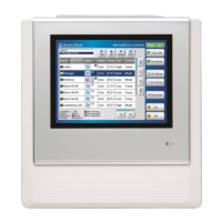
Description of External input/output PCB
To indoor unit PCB
Connector wire
Rotary switch
SW2
SW1
Fig. External input and output PCB
• Connection depends on the PCB type of the indoor unit.
Refer to the installation manual of the indoor unit for details
on how to connect to the indoor unit PCB.
4. SETTINGS
4.1. Connectable devices
External
input/
output
Terminal
block
Input
select
(SW1)
Input
signal
(SW2)
External
input
Operation/
Stop
Input 1/
Input 2
Dry
contact/
Apply
voltage
Edge/Pulse
Forced
thermostat
off
Input 1 Edge
External
output
Operation
status
Output 1
Output 2
Output 3
––
Error status
Indoor unit
fan
operation
status
External
heater
output
■
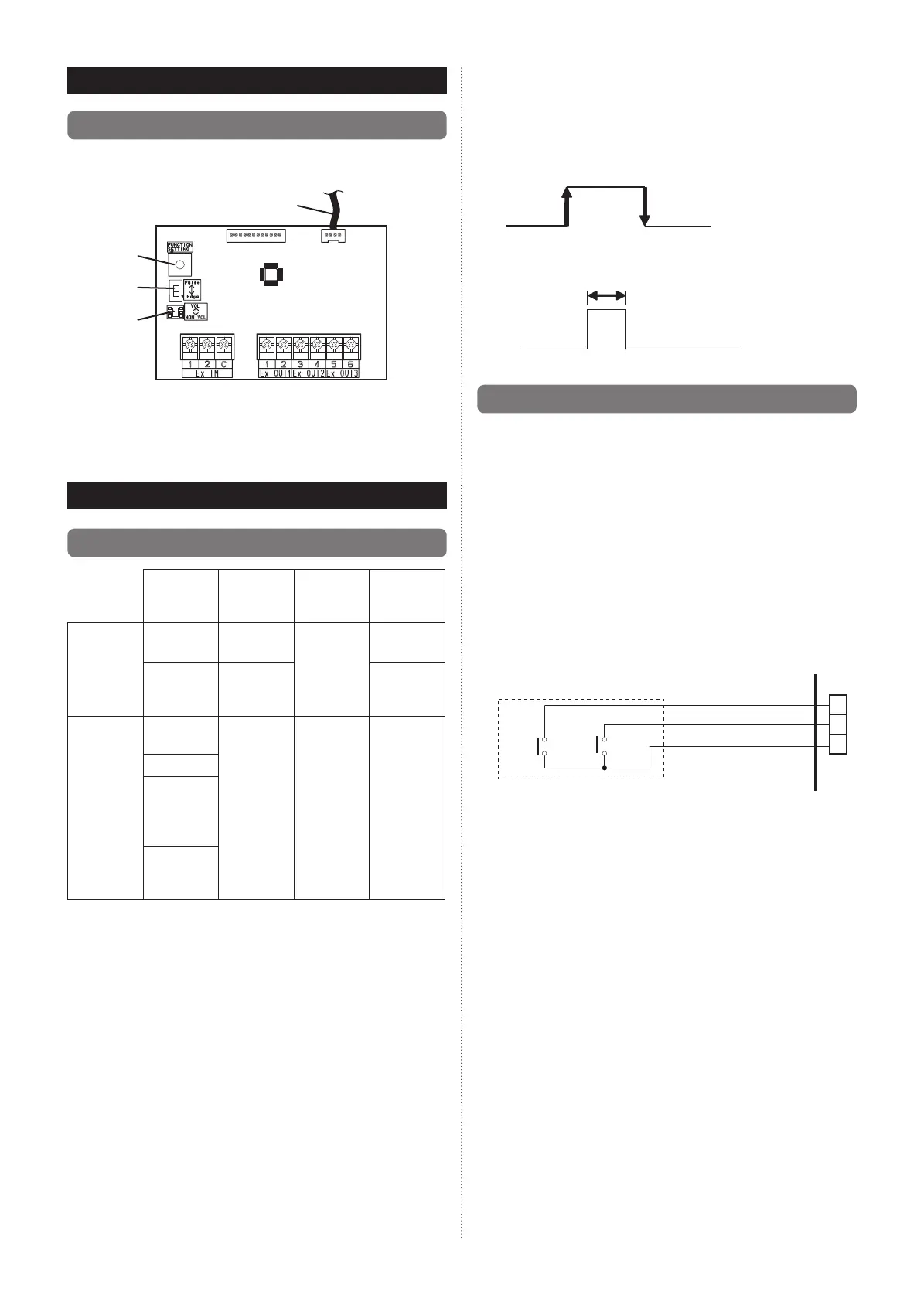
Input signal type
The input signal type can be selected.
Signal type (edge or pulse) can be switched by the DIP
switch 2 (SW2) on the External input and output PCB.
When SW2 is on the “Edge” side.
When SW2 is on the “Pulse” side.
Edge
Pulse
The width of pulse must be longer than 200 msec.
4.2. External input
• “Operation/Stop” mode or “Forced stop” mode can be
selected with function setting of indoor unit.
• A twisted pair cable (22AWG) should be used. Maximum
length of cable is 150 m.
• The wire connection should be separate from the power
cable line.
●
Input select
Use either one of these types of terminals according to
the application. (Both types of terminals cannot be used
simultaneously.)
• Dry contact
In case of internal power supply, set the slide switch of
SW1 to “NON VOL” side.
1
2
C
+
+
-
Input 1
1 1
Input 2
Connected unit
PCB
*1: The switches can be used on the following condition:
DC 12 V to 24 V, 1 mA to 15 mA.
9380828112_IM.indd 29380828112_IM.indd 2 21/4/2017 PM 1:15:2021/4/2017 PM 1:15:20