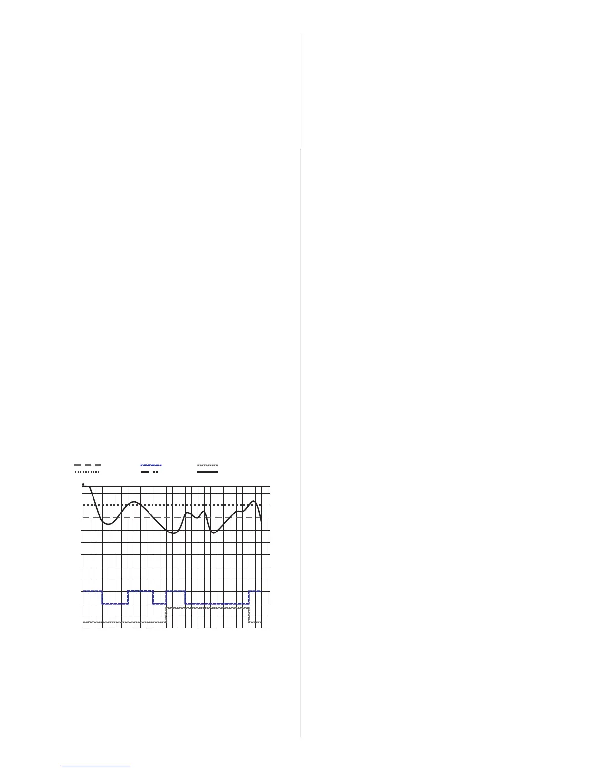
SETPOINT COMPRESSOR AUXILIARY OUTPUT
REFRIGERATION
DIFFERENTIAL
HEATING
DIFFERENTIAL
TEMPERATURE
8
0 1 2 3 4 5 6 7 8 9 10 11 12 13 14 15 16 17 18 19 20 21 22 23 24 25 26 27 28 29
Temperatures
14
12
10
6
4
2
0
On
Off
On
Off
COMP
AUX
4.3 - Parameters description
F01 - Access code
In case the user wants to change the set value in any function, it is necessary to enter access code "123"
in this function. In case you want to visualize the set values, it is not necessary to insert this code.
F02 - Controller operating mode
Set the operating mode of the controller:
- Refrigeration
The compressor goes off when the temperature of sensor S1 is equal to "Setpoint"
The compressor turns on when the temperature of sensor S1 is equal to the Setpoint + (Control
differential (hysteresis) – refrigeration)
- Heating
The compressor goes off when the temperature of sensor S1 is equal to "Setpoint"
The compressor turns on when the temperature of sensor S1 is equal to the Setpoint - (Control
differential (hysteresis) in heating)
- Automatic
In this operating mode the AUX output set for the cycle reversing valve ( =3), and it is not possible
to change the value set in .
In case refrigeration is active (AUX relay off):
The compressor goes off when the temperature of sensor S1 is equal to "Setpoint".
The compressor turns on when the temperature of sensor S1 is equal to the Setpoint + (Control
differential (hysteresis) in refrigeration).
If the temperature drops to the Setpoint - (Control differential (hysteresis) in heating), the cycle is
reversed, and the controller starts to control the temperature by heating the environment. At this point
the AUX relay is switched on. As the COMP relay was already off, since the temperature in S1 was
already lower than the Setpoint, the function (Minimum time for compressor off) will be
respected.
In case the heating is active (AUX relay off):
The compressor goes off when the temperature of sensor S1 is equal to "Setpoint".
The compressor turns on when the temperature of sensor S1 is equal to the Setpoint + (Control
differential (hysteresis) in heating).
If the temperature rises to the Setpoint + (Control differential (hysteresis) in refrigeration), the
cycle is reversed, and the controller starts to control the temperature by cooling the environment. At this
point the AUX relay is switched off. As the COMP relay was already off when the temperature in S1 was
higher than the Setpoint, the function (Minimum time for compressor off) will be respected.
Notes:
If the function is modified, the function is automatically changed according to the
conditions described below:
-If is changed to 0 or 1 (Controller operating mode: Refrigeration or Heating), the function
is automatically modified to 1 (AUX output for alarm) and the user will be able to change this
value to 0, 1, 2 or 3.
-If is changed to 2 (Automatic), the function is automatically modified to 3 (AUX output to
cycle reversing valve) and the user will not be able to change the value of this function (the is
hidden from the functions menu).
[,0,]
[F03]
[,1,]
[F04]
[,2,]
[F43]
[F43]
[F03]
[F04]
[F48]
[F04]
[F04]
[F48]
[F02] [F44]
[F02]
[F44]
[F02] [F44]
[F44]
F03 - Control differential (hysteresis) in refrigeration
It sets the control differential in refrigeration. It is used when the function =0 (refrigeration) or
=2 (automatic).
It is the temperature difference (hysteresis) between TURNING OFF and TURNING BACK ON
heating. Example: You want to control the temperature in 4.0 ºC with differential of 1.0 ºC. Then,
refrigeration will be switched off at 4.0 ºC and switched back on at 5.0 ºC (4.0 + 1.0).
F04 - Control differential (hysteresis) in heating
It sets the control differential in heating. It is used when the function =1 (heating) or =2
(automatic).
It is the temperature difference (hysteresis) between TURNING OFF and TURNING BACK ON
heating. Example: You want to control the temperature in 4.0 ºC with differential of 1.0 ºC. Then,
heating will be switched off at 4.0 ºC and switched back on at 3.0 ºC (4.0 - 1.0).
F05 - Offset indication of ambient temperature
This function allows you to compensate eventual deviations in the ambient temperature reading (S1),
resulting from the change of sensor or modification of the cable length.
[F02]
[F02]
[F02] [F02]
F06 - Offset indication of evaporator temperature
This function allows you to compensate eventual deviations in the evaporator temperature reading (S2),
resulting from the change of sensor or modification of the cable length. In case you want to disable sensor
S2, simply increase the value of this function to the maximum, until the message appears on the
display.
F07 - Minimum setpoint allowed to the end user
F08 - Maximum setpoint allowed to the end user
It sets the minimum and maximum setpoint limits in order to prevent the user from setting an excessively
high or low setpoint temperature by mistake.
F09 – Control delay at start (energizing)
It sets the time at which the controller will remain with its control disabled when you turn it on in order to
delay the start of the process. During this time the controller works only as a temperature indicator. The
purpose of this function is to be able to avoid voltage spikes in case the return of power is necessary and
there are multiple devices connected to the same power supply. To avoid this situation, simply set different
start control delay times for each device. This delay serves both to delay the start of the
refrigeration/heating cycle and to delay defrost at start, in case it is active ( =1).
F10 - Defrost type (Refrigeration)
It sets the type of defrost, in case the controller is working in refrigeration ( =0 or =2):
- Electrical defrost (resistance) or hot gas defrost in refrigeration rack systems (exclusive hot gas
and liquid lines), where only the defrost output is activated.
- Hot gas defrost in plug-in systems (with reversing valve), where the compressor and defrost
outputs are driven. The compressor is necessarily switched off before the defrost cycle starts, respecting
the minimum compressor off time before starting it (in order to reduce coolant waterhammer in the ducts).
- Hot gas defrost in plug-in systems (with reversing valve), where the compressor and defrost
outputs are driven. The compressor is not switched off, in case it is on, before starting the defrost cycle.
F11 - Condition for starting defrost (Refrigeration)
It sets the condition to start defrost, in case the controller is working in refrigeration ( =0 or
=2):
- Defrost start by time
- Defrost start by temperature in S2
In case the defrost start condition is by temperature, when the evaporator temperature reaches the value
set in , the instrument switches to the pre-defrost state.
F12 - Interval between defrosts (Refrigeration)
It sets how often the controller will perform a defrost if it is working in refrigeration ( =0 or =2)
and if the defrost start condition is "Defrost start by time" ( =0). This time begins to run from the
previous defrost (refrigeration mode). Defrost will only start if the temperature in S2 (evaporator sensor) is
lower than that indicated in .
F13 - Interval between defrosts (Heating)
It sets the time in which the controller will perform a defrost, in case it is running in heating ( =1 or
=2), and starts to run from the previous defrost (heating mode).
F14 - Maximum time in refrigeration
It sets the maximum time in which the controller can remain in refrigeration state ( =0 or =2)
before it mandatorily performs a defrost. This function only works if the defrost start condition is "Defrost
start by temperature in S2" ( =1), and if the evaporator temperature (temperature in S2) never
reaches the "Evaporator temperature for defrost start" ( ).
F15 - Temperature in the evaporator for defrost start (Refrigeration)
It sets the necessary evaporator temperature (sensor S2) for the controller to enter the state of pre-
defrost, in case it operates in refrigeration mode ( =0 or =2). This function only works if the
defrost start condition is "Defrost start by temperature in S2" ( =1).
F16 - Time of pre-defrost (Refrigeration)
It sets the time in which the controller will remain in a pre-defrost state, in case it operates in refrigeration
mode ( =0 or =2). This function only works if the defrost start condition is "Defrost start by
temperature in S2" ( =1).
If during all the defrost stage the temperature in S2 remains below the value set in function ,
defrost starts. In case the temperature in S2 increases 1ºC (2ºF) in relation to the temperature set in
, the controller returns to the refrigeration state.
F17 - Time for gas collection in defrost (Heating/Refrigeration)
It sets the time in which the controller will only stay with the fan on at the start of defrost (defrost in
Refrigeration mode Cooling or Heating mode), in order to take advantage of the residual energy of the
gas.
F18 - Defrost at start (Heating/Refrigeration)
This function sets if the controller must perform (or not) defrost at start (controller energizing). The
purpose of this function is to prevent the controller from remaining for too long in refrigeration/heating, in
case there is a failure and energy return.
If the controller is operating in refrigeration mode ( =0), defrost at start only runs if the temperature
in S2 is below the temperature specified in function (Temperature in S2 for end of defrost).
If the controller is operating in heating mode ( =1), defrost at start is run after the start control delay
( ) has elapsed.
If the controller is operating in automatic mode ( =2), defrost at start is disabled.
F19 - Temperature in the evaporator (S2) for end of defrost (Refrigeration)
It sets the necessary evaporator temperature (sensor S2) to complete defrost (refrigeration mode). The
purpose of this function is to optimize the defrost process.
F20 - Maximum defrost time (for safety) (Refrigeration)
It sets the maximum time in which the controller will remain in defrost state (refrigeration mode). If the
temperature in S2 does not reach the value set in during the time set in this function, a dot will be
flashing at the bottom right-hand corner of the display indicating that the end of defrost occurred by time
and not by temperature. This can happen in the following situations:
-If the temperature set in was very high,
-If the time set in was too short
-If sensor S2 is disconnected
-If sensor S2 is disabled ( )
-If sensor S2 is in contact with the evaporator.
[OFF]
[F18]
[F02] [F02]
[,0,]
[,1,]
[,2,]
[F02]
[F02]
[,0,]
[,1,]
[F02] [F02]
[F11]
[F19]
[F02]
[F02]
[F02] [F02]
[F11]
[F15]
[F02] [F02]
F11]
[F02] [F02]
[F11]
[F15]
[F15]
[F02]
[F19]
[F02]
[F09]
[F02]
[F19]
[F19]
[F20]
[F06]=[OFF]
Notes:
1 - Active function if F11=0 (Condition to start defrost (refrigeration mode): time)
2 - Active function if F11=1 (Condition to start defrost (refrigeration mode): temperature)
3 - In item 5.7 it is shown how to determine the final defrost temperature, and the respective recording in
this parameter automatically.
4 - Active function if F26=0 (Fan and compressor operating mode after drainage: control by F27 and
F28).
5 - Active function if F26=1 (Fan and compressor operating mode after drainage: control by F29).
6 - Active function if F30=0 (Fan operating mode during Refrigeration/Heating: Automatic).
7 - The alarms will always be shown on the display, but the AUX output will be activated for alarms only if
F44=1 (AUX output operating mode: Output for alarm)
8- Active function if F43=2 or F43=6 (Digital input operating mode: Door opening, contact (NC) or (NO),
respectively).
 Loading...